Composite bridge expansion joint device

An expansion joint and composite technology, applied in the field of expansion joints, can solve the problems of troublesome operation, low connection tightness and long construction period.

Pending Publication Date: 2020-10-27
CHINA RAILWAY DESIGN GRP CO LTD +1
View PDF1 Cites 0 Cited by
  • Summary
  • Abstract
  • Description
  • Claims
  • Application Information

AI Technical Summary

Problems solved by technology

However, the cavity used for positioning the waterstop is essentially a slot structure, and the ear straps of the waterstop need to be inserted into it forcibly. cost; secondly, the upper and lower parts o...

Method used


Image

  • Composite bridge expansion joint device
  • Composite bridge expansion joint device

Examples


Embodiment Construction

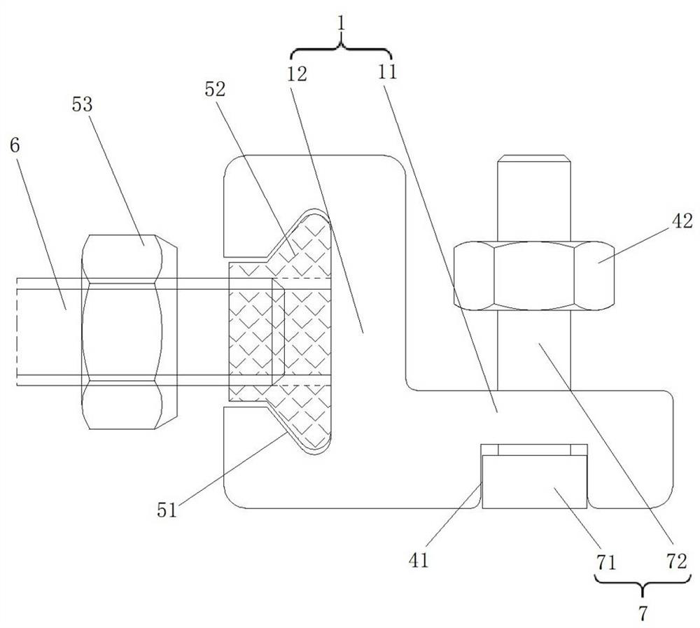
[0018] see figure 1 , figure 2 , is a structural schematic diagram of a composite bridge expansion joint device provided by the present invention. The structure of the composite bridge expansion joint device includes L-shaped steel 1 symmetrically arranged in the beam body b on both sides of the expansion joint a, the flat plate 11 of the L-shaped steel 1 is combined with the pressure plate 2 on it, and the water-stop belt c side ear straps c1 is sealed and fixed, the fastening bolt 7 runs through the pressure plate 2, the ear strap c1 and the plate 11 and locks the pressure plate 2 on the plate 11 through the first limit mechanism 4, between the pressure plate 2 and the ear strap c1 and / or between the ear strap c1 and the An elastic gasket 3 is arranged between the plates 11; the vertical plate 12 of the L-shaped steel 1 fits with the side wall of the reserved notch d of the beam body b, and the outer side of the vertical plate 12 is connected with the anchoring steel bar 6...


PUM


Abstract

The invention belongs to the technical field of expansion joints, and particularly relates to a composite bridge expansion joint device. The device structurally comprises L-shaped steel symmetricallyarranged in beam bodies on the two sides of the expansion joint. A flat plate of the L-shaped steel is combined with a pressing plate on the L-shaped steel to seal and fix a lug belt on the side edgeof a water stop belt, a fastening bolt penetrates through the pressing plate, the lug belt and the flat plate and locks the pressing plate on the flat plate through a first limiting mechanism, and anelastic sealing gasket is arranged between the pressing plate and the lug belt and/or between the lug belt and the flat plate. A vertical plate of the L-shaped steel is attached to the side wall of the reserved notch of the beam body, and the outer side of the vertical plate is connected with an anchoring steel bar through a second limiting mechanism. The composite bridge expansion joint device can be used for quickly mounting and positioning the water stop belt, is convenient for anchoring, mounting and dismounting the cavity, and has the characteristics of firm connection, strict sealing andlong service life.

Description

technical field [0001] The invention belongs to the technical field of expansion joints, and in particular relates to a composite bridge expansion joint device. Background technique [0002] The bridge expansion joint device is installed between adjacent beam ends or at the expansion joint between the beam body and the abutment parapet, which plays the role of adapting to the deformation of the beam end and waterproofing, and is an important accessory of the bridge. In addition to satisfying the free expansion and contraction of the bridge in two directions parallel and perpendicular to the bridge axis, its performance also prevents rainwater and garbage soil from seeping and blocking the telescopic structure, especially to prevent rainwater and sewage from flowing into the beam end and the end of the prestressed anchor head at the beam end. , to avoid the corrosion of prestressed anchors affecting the service life of the beam. [0003] Most of the existing expansion device...

Claims


Application Information

Patent Timeline
IPC IPC(8): E01D19/06E01D101/30E01D101/26E01D101/40
CPCE01D19/06E01D2101/26E01D2101/30E01D2101/40
Inventor 白鸿国李宇孙大斌郭勇侯若敬高双全李淑明黄洪涛金家康赵雅婷郭庆军刘保志王山虎赵荣
Owner CHINA RAILWAY DESIGN GRP CO LTD
Why Eureka
Try Eureka