Tiling device for mosaic tiles
A mosaic and tile technology, which is applied in workpiece clamping devices, decorative arts, decorative structures, etc., can solve the problems of low efficiency and difficulty in manual paving devices.
- Summary
- Abstract
- Description
- Claims
- Application Information
AI Technical Summary
Problems solved by technology
Method used
Image
Examples
Embodiment 1
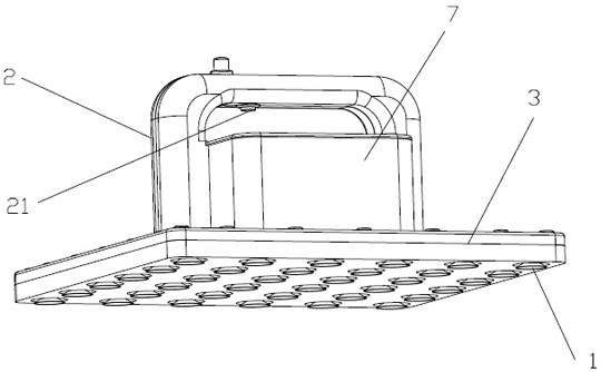
[0026] refer to figure 1 , the embodiment of the present invention provides a mosaic tile laying device, including a suction cup 1 and a handle 2 . A plurality of suction cups 1 are installed on the same vacuum casing 3, and the fixing and loosening of the suction cups 1 and the mosaic tiles are realized by changing the gas volume in the vacuum casing 3. A handle 2 is connected to the vacuum housing 3 . Specifically, the suction cup 1 is fixed horizontally and vertically on the bottom of the vacuum housing 3 . After the suction cup 1 adheres to all the small tiles on the mosaic tiles, the vacuum housing 3 can be manually exhausted. The gas in the vacuum housing 3 is lost, and the suction cup 1 will hold all the small tiles of the mosaic tiles tightly. Holding the handle 2 can carry out the carrying and paving device to the vacuumized casing 3, and this way can keep the whole piece of mosaic tile relatively level. The mosaic tiles laid by the device have good flatness, maki...
Embodiment 2
[0028] In order to improve the degree of automation of the paving device in Embodiment 1, the following functions are added.
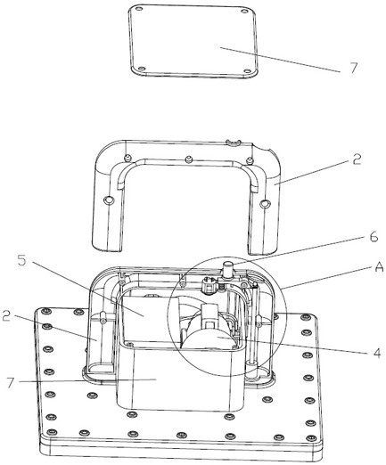
[0029] Further, referring to 2, in an optional embodiment, the vacuum housing 3 is connected with an air pump 4 to realize the air extraction function.
[0030] Further, referring to 2, in an optional embodiment, the air pump 4 is powered by connecting a battery 5 . The degree of automation is improved by controlling the air pump 4 through the battery 5 to extract air.
[0031] Further, see figure 1 with figure 2 , in an optional embodiment, the handle 2 is provided with a switch 21 for controlling the start and stop of the air pump 4 . The start of the air pump 4 is realized by pressing the switch 21 , and the stop of the air pump 4 is realized by stopping the press of the switch 21 . Or select to press switch 21 to start air pump 4, then click switch 21 to close the switch of air pump.
[0032] Further, see figure 1 with figure 2 , in an opt...
Embodiment 3
[0035] On the basis of the second embodiment, the deflation assembly 6 is further optimized.
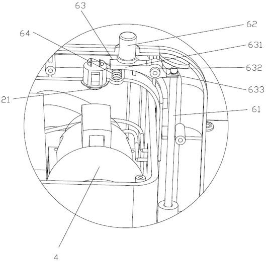
[0036] Further, see figure 2 with image 3 , in an optional embodiment, the deflation assembly 6 also includes a control rod 63 that is clamped on the one-way valve shaft 61 and controls its up and down movement, and connected with the end of the control rod 63 away from the one-way valve shaft 61 Return spring 64.
[0037] Further, see figure 2 with image 3 , in an optional embodiment, the control rod 63 includes a card joint 631 for clamping the one-way valve shaft 61, a rotation slot 632 extending from the side of the card joint 631 away from the one-way valve shaft 61, and a rotation slot 632 away from the rotation slot 632. A rotating arm 633 extending from one side of the snap connector 631 . The rotating arm 633 is connected with the button 62 and the return spring 64 . When the button 62 is not pressed, the return spring 64 is against the rotating arm 633 , and the r...
PUM
 Abstract
Description
Claims
Application Information
 - R&D
- Intellectual Property
- Life Sciences
- Materials
- Tech Scout
- Unparalleled Data Quality
- Higher Quality Content
- 60% Fewer Hallucinations
Browse by: Latest US Patents, China's latest patents, Technical Efficacy Thesaurus, Application Domain, Technology Topic, Popular Technical Reports.
© 2025 PatSnap. All rights reserved.Legal|Privacy policy|Modern Slavery Act Transparency Statement|Sitemap|About US| Contact US: help@patsnap.com


