
Centrifugal pump

A technology for centrifugal pumps and pump shafts, applied in the field of centrifugal pumps, which can solve the problems of high viscosity loss and inability to allow economical and efficient operation.

Inactive Publication Date: 2020-10-27
SULZER MANAGEMENT AG
View PDF2 Cites 2 Cited by
  • Summary
  • Abstract
  • Description
  • Claims
  • Application Information

AI Technical Summary

Problems solved by technology

In effect, these viscous losses limit the motor speed to about 6000rpm
For higher speeds, viscous losses become too high to allow economical and efficient operation of the pump

Method used


Image

  • Centrifugal pump
  • Centrifugal pump
  • Centrifugal pump

Examples


Embodiment Construction

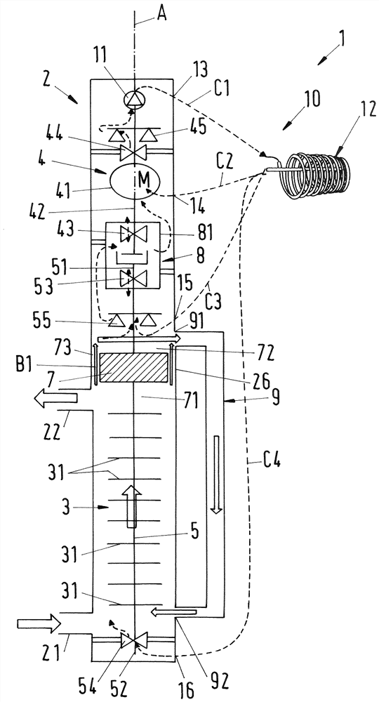
[0041] figure 1 A schematic cross-sectional view of a first embodiment of a centrifugal pump according to the invention is shown, which pump is designated in its entirety by the reference number 1 . For example, the pump 1 is designed as a process fluid lubrication pump for conveying process fluids and has a common housing 2 , a pump unit 3 and a drive unit 4 . Both the pump unit 3 and the drive unit 4 are arranged in a common housing 2 . The common housing 2 is designed as a pressure housing which can withstand the pressure generated by the pump 1 and the pressure exerted on the pump 1 by the environment. The common housing 2 may comprise several housing parts, eg a pump housing and a driver housing, which are connected to each other to form a common housing 2 surrounding the pump unit 3 and the drive unit 4 . The common housing 2 is configured as an airtight pressure housing which prevents any leakage to the external environment.

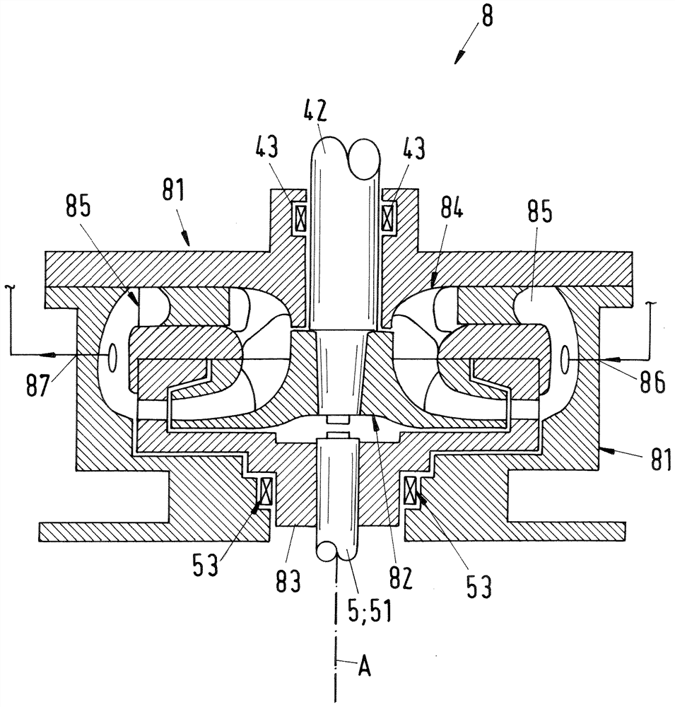
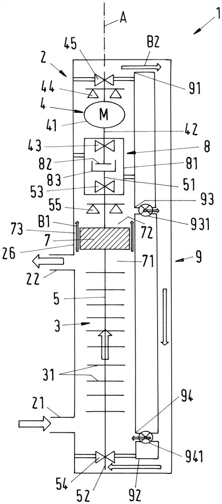
[0042] In the following description refe...


PUM


Abstract

A centrifugal pump for conveying a process fluid is proposed, having a pump unit, a drive unit for driving the pump unit, a pump inlet for receiving the process fluid and a pump outlet for dischargingthe process fluid, wherein the pump unit comprises at least one impeller for conveying the process fluid from the pump inlet to the pump outlet, and a pump shaft, on which each impeller is mounted, wherein the drive unit comprises a drive shaft for driving the pump shaft, and an electric motor for rotating the drive shaft about an axial direction, wherein a plurality of bearings is provided for supporting the pump shaft and the drive shaft, wherein a hydrodynamic coupling having a casing is provided for hydrodynamically coupling the drive shaft to the pump shaft by means of a transmission fluid, and wherein at least one of the plurality of bearings is arranged in the casing of the hydrodynamic coupling.

Description

technical field [0001] The invention relates to a centrifugal pump for conveying process fluids according to the preambles of the independent claims. Background technique [0002] Centrifugal pumps have at least one rotating impeller for conveying process fluid from the pump inlet to the pump outlet. The at least one impeller may be configured as a radial, axial, mixed flow or helical axial impeller. Centrifugal pumps are known in many embodiments, such as single-stage pumps, multi-stage pumps, single-phase pumps or multi-phase pumps, just to name a few. Centrifugal pumps are used in many different industries, for example in the cleaning and wastewater industry, the chemical processing industry or the power generation industry. Another important example is the oil and gas processing industry, where centrifugal pumps are designed, for example, as multiphase pumps for the transfer of hydrocarbon fluids, e.g. for the extraction of crude oil from oil fields or for oil / gas tran...

Claims


Application Information

Patent Timeline
Patent Type & Authority Applications(China)
IPC IPC(8): F04D13/06F04D29/046F04D29/58F04D29/66E21B43/20
CPCE21B43/20F04D13/06F04D29/046F04D29/586F04D29/669F04D1/06F04D13/022F04D13/086F04D29/0416F04D29/0473F04D29/5806F04D1/00F04D29/043F04D29/061F04D29/5813
Inventor T.菲利克斯M.伯尔尼S.嘉斯曼K.德瑞福
Owner SULZER MANAGEMENT AG
Learn More