
Labyrinth sealing device for improved drainage

一种迷宫式密封、密封装置的技术,应用在发动机的密封、运输和包装、旋转运动的轴承等方向,能够解决无法管理轴承单元轴向外侧等问题

Pending Publication Date: 2020-10-27
AB SKF
View PDF14 Cites 0 Cited by
  • Summary
  • Abstract
  • Description
  • Claims
  • Application Information

AI Technical Summary

Problems solved by technology

Unfortunately, this solution does not solve the above problems: due to the design, the discharge hole may only be provided on the axial inside of the bearing unit, although the discharge hole facilitates drainage in that area, it certainly cannot be managed to solve the axial problem of the bearing unit. outside problem

Method used


Image

  • Labyrinth sealing device for improved drainage
  • Labyrinth sealing device for improved drainage
  • Labyrinth sealing device for improved drainage

Examples


Embodiment Construction

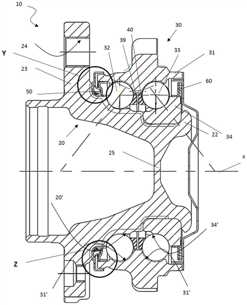
[0018] Now, purely by way of non-limiting example, the invention will be described with reference to a wheel hub assembly for a motor vehicle provided with a bearing unit having a sealing arrangement according to the invention.

[0019] refer to figure 1 , a wheel hub assembly according to a preferred embodiment of the present invention is indicated generally by 10 . The drawings show details of construction provided by way of example.

[0020] The assembly 10 has a central axis of rotation X and comprises a rotating hub 20 and a bearing unit 30 which in turn comprises:

[0021] - a stationary radial outer ring 31;

[0022] - a radially inner ring 22 defined by the hub 20;

[0023] - another radially inner ring 34 of rotation, mounted on and integral with the hub 20;

[0024] - two rows of rolling bodies 32, 33 arranged between the radially outer ring 31 and the radially inner ring 22, 34, rolling bodies 32, 33 being balls in this example; and

[0025] - Two cages 39 and ...


PUM


Abstract

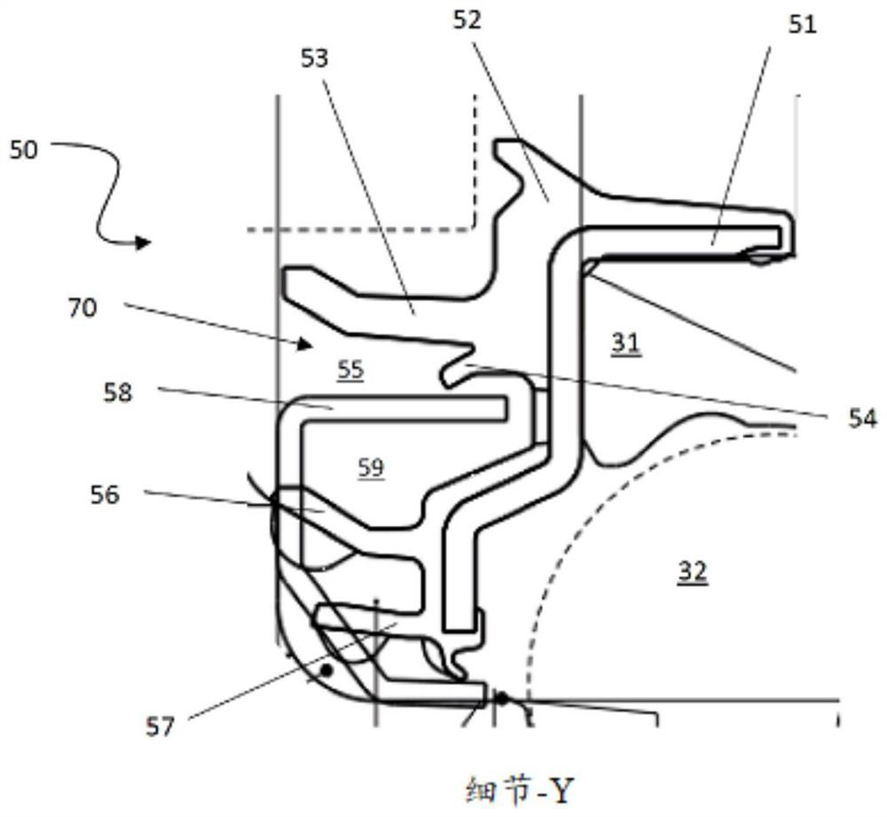
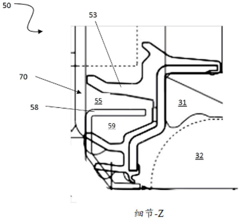
A sealing device (50) for a bearing unit (30) has a static component (70) and a rotatable metallic shield (58), wherein the static component (70) comprises a shaped metallic support (51) and at leastone lip (56, 57), a first lip (53) and a second lip (54) not making contact with the metallic shield (58) are co-moulded on the shaped metallic support (51), the at least one lip (56, 57) is in contact with the metallic shield (58), wherein the second lip (54) and the metallic shield (58) define a labyrinth seal. The second lip (54) has an angular extension range of less than 360 degrees, so thatcontaminants are discharged from the inside of the sealing device (50) along the missing corner portion of the second lip (54).

Description

technical field [0001] The present invention relates to a cartridge seal having innovative features that allow improved discharge from the seal of contaminants that have entered the interior of the seal. This sealing device is applied to the bearing unit. The invention is particularly, but not exclusively, applicable to a wheel hub assembly of a motor vehicle, said wheel hub assembly being provided with a bearing unit. More specifically, the bearing unit according to the present invention is a bearing unit in which the outer ring of the bearing is stationary and the inner ring of the bearing is rotatable. The invention applies advantageously, but not exclusively, to bearing units with double rows of balls. Background technique [0002] As is well known, bearing units are often exposed to various types of contaminants (eg, mud ( / mud / mud), dust and suspended particulate matter and / or particles in solution). Bearing units, including those shaped parts of wheel hub assemblies...

Claims


Application Information

Patent Timeline
Patent Type & Authority Applications(China)
IPC IPC(8): F16C33/80
CPCF16C33/80F16C33/805F16C19/186F16C33/7823F16C33/7886F16C2240/30F16C2326/02F16J15/3264F16J15/3456F16J15/4476B60B27/0073F16C19/08F16C33/726
Inventor 安东尼亚·纳斯塔西保罗·阿雷
Owner AB SKF
Learn More