A mirror-symmetrical loop heat pipe

A technology of loop heat pipes and tube groups, applied in tubular elements, heat transfer modification, indirect heat exchangers, etc., can solve the problems of insufficient heat transfer uniformity of heat pipes, low heat transfer capacity of heat pipes, uneven heat transfer, etc. Achieve the effects of increasing the vibration range, enhancing heat transfer, and optimizing structural parameters

Inactive Publication Date: 2021-08-13
SHANDONG UNIV
View PDF6 Cites 0 Cited by
  • Summary
  • Abstract
  • Description
  • Claims
  • Application Information

AI Technical Summary

Problems solved by technology

However, the heat transfer uniformity of the above-mentioned heat pipe is not enough, condensation is only carried out on one side, and the heat transfer amount is also small, so it needs to be improved and a heat pipe system with a new structure should be developed
[0005] In view of the above problems, the present invention improves on the basis of the previous invention, and provides a new heat pipe, so as to solve the problem of low heat transfer and uneven heat transfer of the heat pipe

Method used


Image

  • A mirror-symmetrical loop heat pipe
  • A mirror-symmetrical loop heat pipe
  • A mirror-symmetrical loop heat pipe

Examples


Embodiment Construction

[0026] The specific embodiments of the present invention will be described in detail below in conjunction with the accompanying drawings.

[0027] In this article, if there is no special explanation, when it comes to formulas, " / " means division, and "×" and "*" mean multiplication.

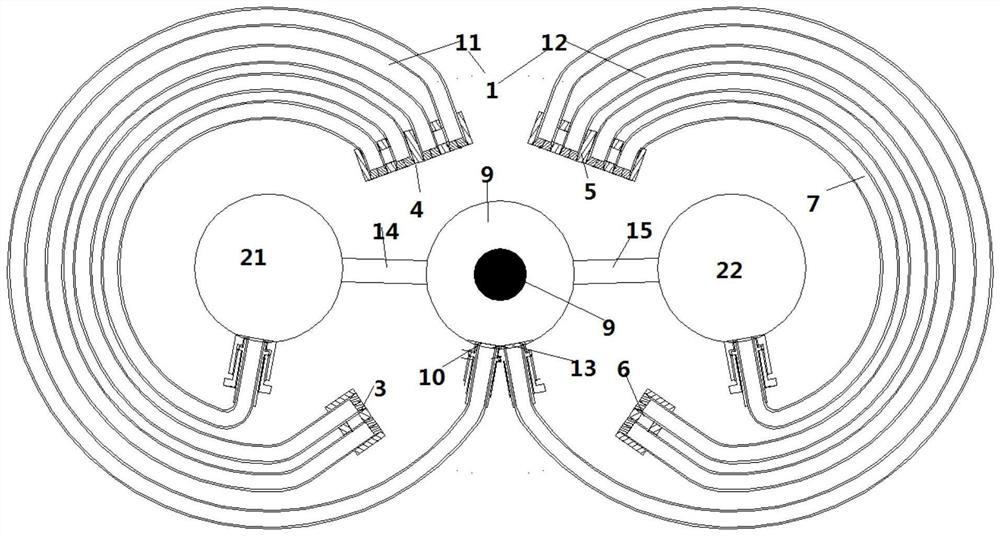
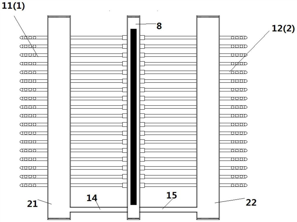
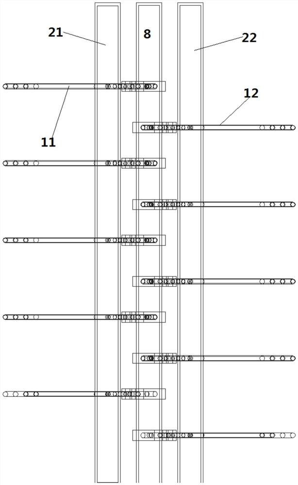
[0028] Such as figure 1 As shown, a loop heat pipe includes a middle evaporation tube 8, a left header 21, a right header 22 and a tube group 1, and the tube group 1 includes a left tube group 11 and a right tube group 12, and the left tube group 11 and the right tube group 12 The left header 21 communicates with the middle evaporation tube 8, and the right tube group 12 communicates with the right header 22 and the middle evaporation tube 8, so that the middle evaporation tube 8, the left header 21, the right header 22 and the tube group 1 form The heating fluid is in a closed cycle, the middle evaporation tube 8 is filled with phase change fluid, the electric heater 9 is arranged in the middle...


PUM


Abstract

The invention provides a loop heat pipe, which includes a middle evaporation tube, a left header, a right header and a tube group, the middle evaporation tube includes a first nozzle and a second nozzle, and the first nozzle is connected to the inlet of the left tube group , the second nozzle is connected to the inlet of the right tube group, the outlet of the left tube group is connected to the left header, and the outlet of the right tube group is connected to the right header; the first outlet and the second outlet are arranged on one side of the middle evaporation tube; The tube group and the right tube group are mirror-symmetrical along the plane where the axis of the central evaporating tube is located. The invention proposes a vibrating tube bundle loop heat pipe with a new structure. By arranging more tube groups in a limited space, the vibration range of the tube bundle is increased, thereby enhancing heat transfer and descaling.

Description

technical field [0001] The invention relates to a loop heat pipe, in particular to an elastic vibration vibration descaling type loop heat pipe. Background technique [0002] Heat pipe technology is a heat transfer element called "heat pipe" invented by George Grover of Los Alamos National Laboratory in the United States in 1963. It makes full use of the principle of heat conduction and phase change medium. The rapid heat transfer properties of the heat pipe quickly transfer the heat of the heating object to the heat source, and its thermal conductivity exceeds that of any known metal. [0003] Heat pipe technology was widely used in aerospace, military and other industries before. Since it was introduced into the radiator manufacturing industry, people have changed the traditional radiator design ideas and got rid of the single heat dissipation mode that only relies on high air volume motors to obtain better heat dissipation. The use of heat pipe technology enables the rad...

Claims


Application Information

Patent Timeline
Patent Type & Authority Patents(China)
IPC IPC(8): F28D15/02F28F1/00F28F13/06F28F19/00
CPCF28D15/0266
Inventor 郭春生江程李佳航张茜卓姜鲲辛稀龙徐怡平纪文睿许东方
Owner SHANDONG UNIV
Why Eureka
Try Eureka