A method for controlling heating of a loop heat pipe system according to temperature

A temperature control and loop heat pipe technology, applied in the field of heat pipes, can solve the problems of uneven heat absorption, occupancy, and low fluidity, and achieve the effects of increasing the vibration range, optimizing the best relationship, and improving heat exchange efficiency

Active Publication Date: 2021-10-15
ZHONGBEI UNIV
View PDF0 Cites 0 Cited by
  • Summary
  • Abstract
  • Description
  • Claims
  • Application Information

AI Technical Summary

Problems solved by technology

[0004] In the prior art, the shape of the heat pipe affects the heat-absorbing area of ​​the evaporating end, so the heat-absorbing range of the evaporating end is generally relatively small, and sometimes it is necessary to install multiple heat pipes in the heat source to meet the heat-absorbing demand; and when there are multiple evaporating ends, Because each evaporation end is in a different position of the heat source, it will produce uneven heat absorption.
In the prior art, the waste heat utilization heat pipe device always extends the condensation end to the outside of the pipe, which occupies the external area, making the heat pipe waste heat utilization system not compact
[0005] In addition, elastic vibrating tube bundles are widely used in waste heat heat exchange. In the application, it is found that continuous heating will lead to the stability of the fluid in the internal heat pipe device, that is, the fluid no longer flows or has little fluidity, or the flow rate is stable, resulting in disk The vibration performance of the tube is greatly weakened, which affects the descaling of the coil and the efficiency of heating
[0006] However, in the application, it is found that continuous waste heat heating will lead to the stability of the fluid in the internal loop heat pipe, that is, the fluid no longer flows or has little fluidity, or the flow rate is stable, resulting in a greatly weakened vibration performance of the coil, which affects the coil. Descaling of tubes and heating efficiency
[0007] In practice, it is found that if the vibration of the tube bundle is adjusted through fixed periodic changes, there will be hysteresis and the period will be too long or too short

Method used


Image

  • A method for controlling heating of a loop heat pipe system according to temperature
  • A method for controlling heating of a loop heat pipe system according to temperature
  • A method for controlling heating of a loop heat pipe system according to temperature

Examples


Embodiment Construction

[0036] The specific embodiments of the present invention will be described in detail below in conjunction with the accompanying drawings.

[0037] In this article, if there is no special explanation, when it comes to formulas, " / " means division, and "×" and "*" mean multiplication.

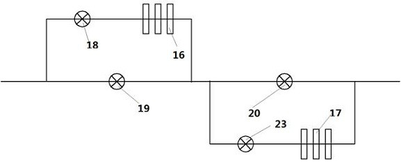
[0038] figure 1 A schematic diagram of the pipe structure of the waste heat utilization loop heat pipe of the present invention is disclosed. Such as figure 1 As shown, the flue gas pipeline 101 includes two bypass pipelines, a first bypass pipeline and a second bypass pipeline, wherein a first valve 18 and a heat pipe 16 are respectively arranged on the first bypass pipeline, and the first bypass pipeline The second valve 19 is set on the flue gas pipeline 101 corresponding to the pipeline. By setting the first valve 18 and the second valve 19, it is possible to control whether the flue gas passes through the heat pipe 16 for waste heat utilization. Wherein, the fourth valve 23 and the heat p...


PUM


Abstract

The invention provides a method for controlling heating of a loop heat pipe system according to temperature. A temperature sensing element is arranged inside the first heat pipe and the second heat pipe to detect the temperature inside the electric heating device. The temperature sensing element communicates with the controller for data connected, the controller controls whether the flue gas heats the first heat pipe and the second heat pipe according to the detected temperature. In the present invention, the temperature detected by the temperature sensing element can satisfy a certain temperature, the evaporation of the internal fluid is basically saturated, and the volume of the internal fluid basically does not change much. In this case, the internal fluid is relatively stable. When the vibration of the tube bundle becomes worse, it needs to be adjusted to make it vibrate, so as to stop heating and switch to another heat pipe for heating. As a result, according to the temperature, the heat pipe is continuously heated alternately, thereby forming constant vibration descaling and heat exchange of the heat pipe.

Description

technical field [0001] The invention relates to a heat pipe technology, in particular to a heat pipe with a new structure. Background technique [0002] Heat pipe technology is a heat transfer element called "heat pipe" invented by George Grover of Los Alamos National Laboratory in the United States in 1963. It makes full use of the principle of heat conduction and phase change medium. The rapid heat transfer properties of the heat pipe quickly transfer the heat of the heating object to the heat source, and its thermal conductivity exceeds that of any known metal. [0003] Heat pipe technology was widely used in aerospace, military and other industries before. Since it was introduced into the radiator manufacturing industry, people have changed the traditional radiator design ideas and got rid of the single heat dissipation mode that only relies on high air volume motors to obtain better heat dissipation. The use of heat pipe technology enables the radiator to obtain a sati...

Claims


Application Information

Patent Timeline
Patent Type & Authority Patents(China)
IPC IPC(8): F28D15/02F28D15/06
CPCF28D15/0266F28D15/06
Inventor 仝志辉李海桥刘汉涛李世民杨宇杰李超张学清
Owner ZHONGBEI UNIV
Why Eureka
Try Eureka