Optical scanning assembly and laser radar

An optical scanning and component technology, applied in the field of optical scanning, can solve the problems of high production cost, large volume, and large number of components

Pending Publication Date: 2020-10-27
HUAWEI TECH CO LTD
View PDF5 Cites 6 Cited by
  • Summary
  • Abstract
  • Description
  • Claims
  • Application Information

AI Technical Summary

Problems solved by technology

[0003] The embodiment of the present application provides an optical scanning component and a laser radar, which can solve the problems of large number, large volume and high production cost of the existing laser radar components while ensuring the scanning accuracy

Method used


Image

  • Optical scanning assembly and laser radar
  • Optical scanning assembly and laser radar
  • Optical scanning assembly and laser radar

Examples


Embodiment Construction

[0036] The following will clearly and completely describe the technical solutions in the embodiments of the application with reference to the drawings in the embodiments of the application. Apparently, the described embodiments are only some of the embodiments of the application, not all of them. Based on the embodiments in this application, all other embodiments obtained by persons of ordinary skill in the art without creative efforts fall within the protection scope of this application.

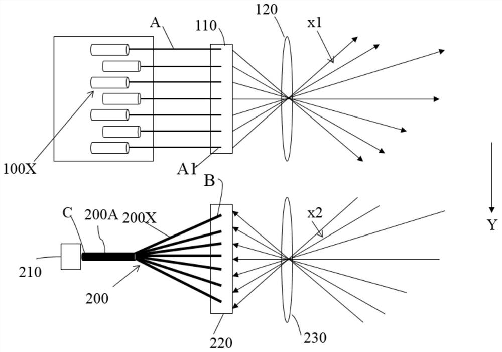
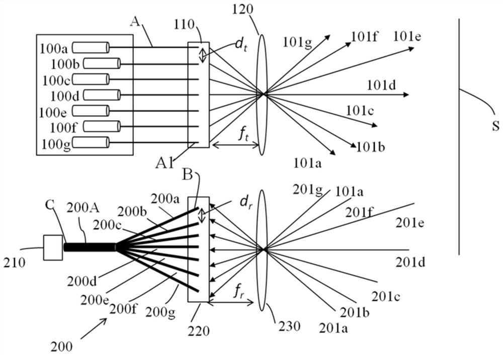
[0037] see figure 1 and figure 2 , the optical scanning assembly provided by the embodiment of the present application is used for the scanning measurement of lidar, and the optical scanning assembly includes n spaced apart lasers 100X, a detector 210, a transmitting optical lens 120, a receiving optical lens 230, and an optical coupling Part 200 ; the transmitting optical lens 120 and the receiving optical lens 230 are arranged at intervals in the first direction and their optical axes a...


PUM


Abstract

The invention provides an optical scanning assembly which can be used in the field of laser radar and networked vehicles and comprises n lasers arranged at intervals, a detector, a transmitting optical lens, a receiving optical lens and an optical coupling part, and n is an integer larger than 1. Each laser is provided with a transmitting end, and the transmitting ends are positioned on a focal plane of the transmitting optical lens and are arranged at intervals. The optical coupling part comprises n receiving channels, the n receiving channels are in one-to-one correspondence with the n transmitting ends, the n receiving ends are located on the focal plane of the receiving optical lens and are arranged at intervals, and the output ends of the n receiving channels are closely arranged andare in butt joint with the detector, the n lasers transmit laser beams in a time-sharing mode, and the laser beams are emitted out at different angles after entering the transmitting optical lens through the transmitting ends. The receiving optical lens receives n echo light beams generated by the n laser beams and focuses the echo light beams to the corresponding output ends so as to transmit theecho light beams into the detector through the output ends.

Description

technical field [0001] The present application relates to the field of optical scanning technology, in particular to an optical scanning component and a laser radar. Background technique [0002] Lidar with a large field of view and a high number of scanning lines is an indispensable road condition sensing device for future automatic machine positioning technology and unmanned vehicle technology. At present, the number of scanning lines of the common lidar is 16 lines, in which 16 sets of lasers and 16 sets of detectors are used for one-to-one transmission. With the increase of collected data, it is necessary to increase the number of lasers and detectors to achieve the accuracy of lidar measurement. In order to obtain a higher number of scanning lines for this kind of lidar, the system needs to consume a large number of components, such as lasers, detectors and driving circuits, etc., which increases the size and cost of the lidar. Contents of the invention [0003] The...

Claims


Application Information

Patent Timeline
Patent Type & Authority Applications(China)
IPC IPC(8): G01S17/93G01S17/931G01S17/06G01S7/481
CPCG01S17/93G01S17/06G01S7/4817G01S7/4818G01S7/4815G01S7/4816G01S17/931G01S7/481G01S17/08
Inventor 史光远肖新华
Owner HUAWEI TECH CO LTD
Why Eureka
Try Eureka