Photovoltaic curtain wall assembly and power generation wall system

A photovoltaic and curtain wall technology applied in the field of photovoltaic buildings

Pending Publication Date: 2020-10-27
BEIJING HANERGY PV TECH CO LTD
View PDF0 Cites 0 Cited by
  • Summary
  • Abstract
  • Description
  • Claims
  • Application Information

AI Technical Summary

Problems solved by technology

However, at present, the LED and solar power supply systems are two independent systems, and the solar power supply system needs to lay a large area of ​​solar cell components in order to ensure a high power generation, so it is difficult to combine it with LED

Method used


Image

  • Photovoltaic curtain wall assembly and power generation wall system
  • Photovoltaic curtain wall assembly and power generation wall system
  • Photovoltaic curtain wall assembly and power generation wall system

Examples


Embodiment 1

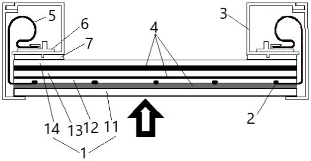
[0027] A photovoltaic curtain wall assembly, comprising: a photovoltaic LED assembly 1 and a fixing frame 3 for fixing the photovoltaic LED assembly 1; the photovoltaic LED assembly 1 includes a front plate 12, a solar chip 13, and a back plate 14 arranged in sequence; the The front panel 12 includes a light-transmitting substrate, a light-transmitting conductive circuit located on the side of the light-transmitting substrate facing away from the solar chip 13, and a plurality of LEDs 2 arranged on the light-transmitting conductive circuit, and the LEDs 2 face outdoors. One side is also provided with a light-transmitting LED protective layer 11; the fixed frame 3 covers at least a part of the edge of the photovoltaic LED assembly 1, and the fixed frame 3 and at least a part of the edge of the photovoltaic LED assembly 1 Constitute an accommodation cavity, the accommodation cavity is used to accommodate the wires 5 of the photovoltaic LED assembly 1, and the energy storage devic...

Embodiment 2

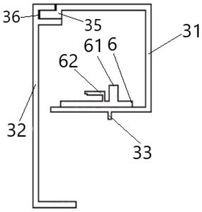
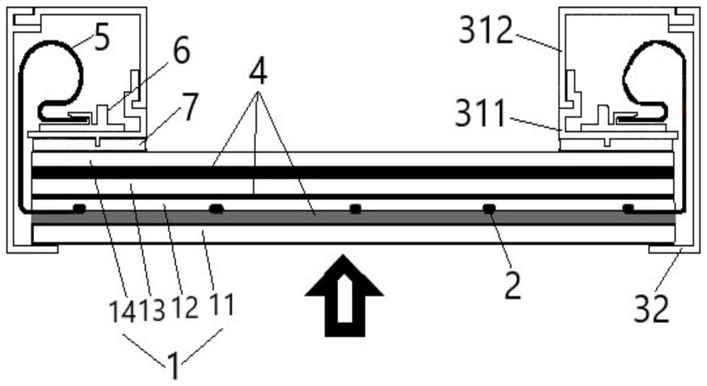
[0034] This embodiment includes all the technical features of the first embodiment, and differs from the first embodiment only in the structure of the fixing frame 3 . Therefore, in this embodiment, the same technical features as in Embodiment 1 will not be repeated, and the main combination image 3 and Figure 4 The structure of the fixing frame 3 of this embodiment will be described. In this embodiment, the fixed frame 3 is still composed of the clamping frame 32 and the accommodating frame 31, the difference is that the accommodating frame 31 is composed of two parts, which include the first accommodating frame 311 and the accommodating frame 31. The second accommodating frame 312 , the first accommodating frame 311 , the second accommodating frame 312 and the engaging frame 32 jointly enclose an accommodating cavity. The first accommodating frame 311 is connected to the end of the backboard 14 facing the indoor side, preferably arranged at two mutually symmetrical ends ...

Embodiment 3

[0040] Embodiment 3 of the present invention provides a power generation wall system, which is integrally assembled on a structural wall of a building. Specifically, the power generation wall system includes photovoltaic curtain walls arranged in a matrix and a skeleton fixed on the structural wall. Wherein, each photovoltaic curtain wall can be the photovoltaic curtain wall described in any one of the above embodiments, and the photovoltaic curtain wall is fixed on the framework.


PUM


Abstract

The invention discloses a photovoltaic curtain wall assembly. The photovoltaic curtain wall assembly comprises a photovoltaic LED assembly and a fixing frame used for fixing the photovoltaic LED assembly, wherein the photovoltaic LED assembly comprises a front plate, a solar chip and a back plate which are arranged in sequence; the front plate comprises a light-transmitting substrate, a conductivecircuit located on the side, which deviates from the solar chip, of the light-transmitting substrate and a plurality of LEDs arranged on the conductive circuit, and an LED protection layer is furtherarranged on the side, which faces the outside, of each LED; the fixing frame wraps at least one part of the edge of the photovoltaic LED assembly to form an accommodating cavity, and an energy storage device and a control device are arranged in the accommodating cavity. According to the solar curtain wall assembly, the solar chip and the LEDs are combined, and the light emitting and displaying functions of the solar curtain wall assembly are achieved. The solar curtain wall assembly not only has building attributes, but also can display static or dynamic pictures, has electronic and multimedia display functions, and widens the application field of the solar curtain wall assembly.

Description

technical field [0001] The invention relates to the technical field of photovoltaic buildings, in particular to a photovoltaic curtain wall. Background technique [0002] LED display technology is widely used in building night scene lighting and outdoor electronic advertising display boards, but LED consumes a lot of power, causing great pressure on energy and the environment, and LEDs are usually directly connected to the mains, the circuit is complex, not only prone to accidents, It also affects the aesthetics of buildings. In addition, the LEDs in the prior art are usually directly exposed to the external environment, and are exposed to wind, heat, and sun. During long-term use, it is easy to cause aging and discoloration of the LEDs, which seriously affects the luminous efficiency and color contrast of the entire system. There will be safety problems such as LED falling off or leakage. As we all know, solar energy is a widely used clean energy, which converts solar ene...

Claims


Application Information

Patent Timeline
Patent Type & Authority Applications(China)
IPC IPC(8): H02S20/26H02S40/38E04B2/88H01L31/12
CPCE04B2/88H01L31/125H02S20/26H02S40/38Y02B10/10Y02E10/50Y02E70/30
Inventor 岳卫东李秀祖杨世忠
Owner BEIJING HANERGY PV TECH CO LTD
Why Eureka
Try Eureka