Supercharge Your Innovation With Domain-Expert AI Agents!

Pulse generation circuit

A technology for generating circuits and generating circuits, which can be used in pulse generation, electrical pulse generation, pulse shaping, etc., and can solve problems such as system clock misoperation and clock duty cycle changes.

Pending Publication Date: 2020-10-27
SEMICON MFG INT (SHANGHAI) CORP +1
View PDF0 Cites 0 Cited by
  • Summary
  • Abstract
  • Description
  • Claims
  • Application Information

AI Technical Summary

Problems solved by technology

[0003] In the IP and system interface communication protocol, there are often their own timing restrictions. The misoperation of the system clock, for example, the change of the clock duty cycle, etc., has a major impact on whether the data read out from the IP is correct.

Method used


Image

  • Pulse generation circuit
  • Pulse generation circuit
  • Pulse generation circuit

Examples


Embodiment Construction

[0032] It can be seen from the background art that how to change the pulse width of the output pulse signal has become an urgent problem to be solved.

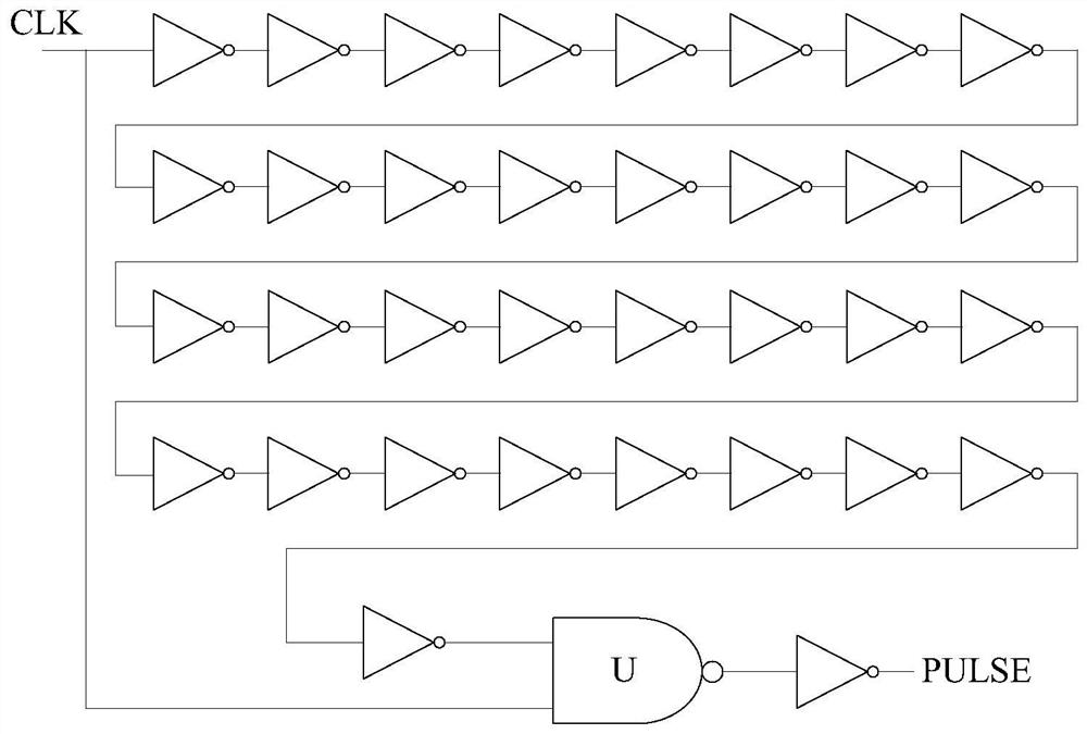
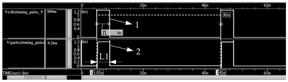
[0033] refer to figure 1 , in a pulse generating circuit, an initial clock signal CLK is input into a digital circuit, and a pulse signal PULSE is output after being delayed by the digital circuit. The digital circuit may include a plurality of inverters and a NAND gate, the plurality of inverters and the NAND gate are connected in series, and the output pulse signal PULSE changes following the change of the initial clock signal CLK. refer to figure 2 A waveform diagram of a pulse signal generated by a pulse generation circuit is shown, wherein 1 is the waveform of the initial clock signal CLK, 2 is the waveform of the output pulse signal PULSE, and the pulse width of the pulse signal PULSE is the same as the pulse width of the initial clock signal CLK Consistently, the pulse width L1 of the pulse signal PULSE is affected b...


PUM


Abstract

The embodiment of the invention discloses a pulse generation circuit. The pulse generation circuit comprises a control circuit and a pulse signal generation circuit, the control circuit is suitable for accessing a pulse signal generated by the pulse signal generation circuit, the control circuit is suitable for responding to a first edge of the pulse signal and delaying to output a second edge ofa control signal, and the jumping direction of the second edge is opposite to that of the first edge; the pulse signal generation circuit is suitable for accessing a clock signal and the control signal, and the pulse signal generation circuit is suitable for generating a first edge of the pulse signal along with a first edge of the clock signal and generating a second edge of the pulse signal along with a second edge of the control signal. According to the technical scheme in the embodiment of the invention, the pulse width of the output pulse signal can be changed.

Description

technical field [0001] The invention relates to the field of circuits, in particular to a pulse generating circuit. Background technique [0002] The emergence of non-volatile memory (Non-volatile memory, NVM) provides a new way for expanding computer memory, and is widely used in various system-on-chip (System on Chip, SOC). [0003] In the IP and system interface communication protocol, there are often their own timing restrictions. The misoperation of the system clock, for example, the change of the clock duty cycle, etc., has a major impact on whether the data read out from the IP is correct. [0004] How to change the pulse width of the output pulse signal has become an urgent problem to be solved. Contents of the invention [0005] The problem solved by the present invention is to change the pulse width of the output pulse signal. [0006] In order to solve the above problems, the present invention provides a pulse generation circuit, including: a control circuit a...

Claims


Application Information

Patent Timeline
Patent Type & Authority Applications(China)
IPC IPC(8): H03K3/353H03K5/04
CPCH03K3/353H03K5/04
Inventor 彭家旭
Owner SEMICON MFG INT (SHANGHAI) CORP
Features
  • R&D
  • Intellectual Property
  • Life Sciences
  • Materials
  • Tech Scout
  • Unparalleled Data Quality
  • Higher Quality Content
  • 60% Fewer Hallucinations
Learn More