
Broadband frequency response measuring method and broadband frequency response measuring device

A frequency response and measurement method technology, applied in transmission monitoring, electrical components, transmission systems, etc., can solve problems such as being unsuitable for practical applications, taking a long time, and affecting the speed of amplitude-frequency response measurement.

Active Publication Date: 2020-10-27
SHENZHEN CITY SIGLENT TECH
View PDF10 Cites 8 Cited by
  • Summary
  • Abstract
  • Description
  • Claims
  • Application Information

AI Technical Summary

Problems solved by technology

On the one hand, the frequency sweep method requires sweeping at equal intervals. The size of the frequency step not only affects the speed of amplitude-frequency response measurement, but also affects the measurement accuracy and final calibration accuracy. If the sweep frequency step is set too small, the acquisition It takes a long time to simulate the amplitude-frequency response of the channel, which affects the measurement and calibration efficiency, and if the frequency sweep step is too large, the obtained amplitude-frequency characteristic response curve may not be able to represent the real channel characteristics; another On the one hand, this method of using a single tone signal as a calibration signal can only obtain the amplitude-frequency response of the analog channel, but cannot obtain the phase-frequency response of the analog channel
In addition, there is still a third technical problem. This frequency sweep method based on a single tone signal cannot effectively obtain the wideband amplitude-frequency characteristics and phase-frequency characteristics of analog devices such as amplifiers, filters, and mixers in the analog channel. Characteristics, for example, for some high-order broadband modulation signals such as high-order QAM signals, the slight amplitude unevenness and nonlinear phase of the analog channel will degrade the signal quality, resulting in the inability to demodulate the transmitted or received signal; specifically , when measuring a bandwidth of 2Δf (such as [f c -Δf,f c +Δf]) for the frequency response of the analog channel, if the frequency sweep method based on a single tone signal is used, since the signal generator or the mixer in the receiver always works at the center frequency f c Therefore, only the amplitude-frequency characteristics at the center frequency can be obtained each time, but the amplitude-frequency characteristics at other frequency points within the bandwidth cannot be obtained
[0005] For another example, another existing technology is to use white noise as a signal source to measure the broadband frequency response of an analog channel. This method utilizes the characteristic that the power spectral density of white noise is evenly distributed in the entire frequency band, and the acquisition is performed in the receiver. To estimate the power spectrum of the noise signal passing through the channel under test, it is necessary to use the average value of multiple estimation results to obtain an approximate amplitude-frequency response, and the phase-frequency response of the analog channel cannot be obtained
There are also some problems in this measurement method. Because the power spectrum of white noise only has the characteristics of uniform distribution, the amplitude-frequency characteristics of the spectrum itself are not flat, but present "noise" characteristics. Therefore, the use of white noise to realize the analog channel The frequency response of the frequency response requires a very large number of average processing, which is not suitable for practical applications, especially for the application of broadband high-order modulation signals

Method used


Image

  • Broadband frequency response measuring method and broadband frequency response measuring device
  • Broadband frequency response measuring method and broadband frequency response measuring device
  • Broadband frequency response measuring method and broadband frequency response measuring device

Examples


Embodiment 1

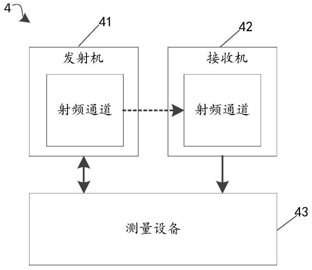
[0054] Please refer to figure 1 , the present application discloses a broadband frequency response measurement device 4, which mainly includes a transmitter 41, a receiver 42 and a measurement device 43, which will be described separately below.

[0055] The transmitter 41 includes a radio frequency channel for generating a transmission signal in response to the first processed signal of the ZC sequence through its own radio frequency channel.

[0056] The receiver 42 also includes a radio frequency channel, its own radio frequency channel is connected to the radio frequency channel of the transmitter 41, and is used to generate an output signal in response to the transmitted signal through its own radio frequency channel.

[0057] The measuring device 43 is connected with the transmitter 41 and the receiver 42, and is used to generate the ZC sequence and transmit the ZC sequence to the radio frequency channel of the receiver after the first processing, for obtaining the outpu...

Embodiment 2

[0072] Please refer to Figure 4 , on the basis of the measuring device 4 disclosed in Embodiment 1, the present application proposes a wideband frequency response measuring method, which mainly includes steps S100-S200.

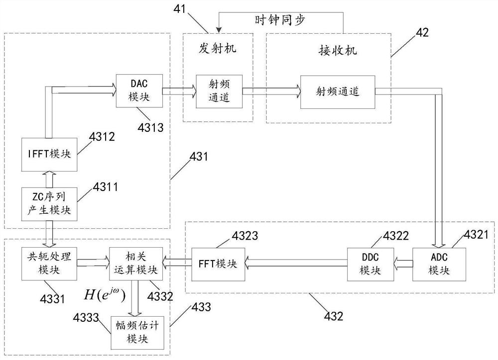
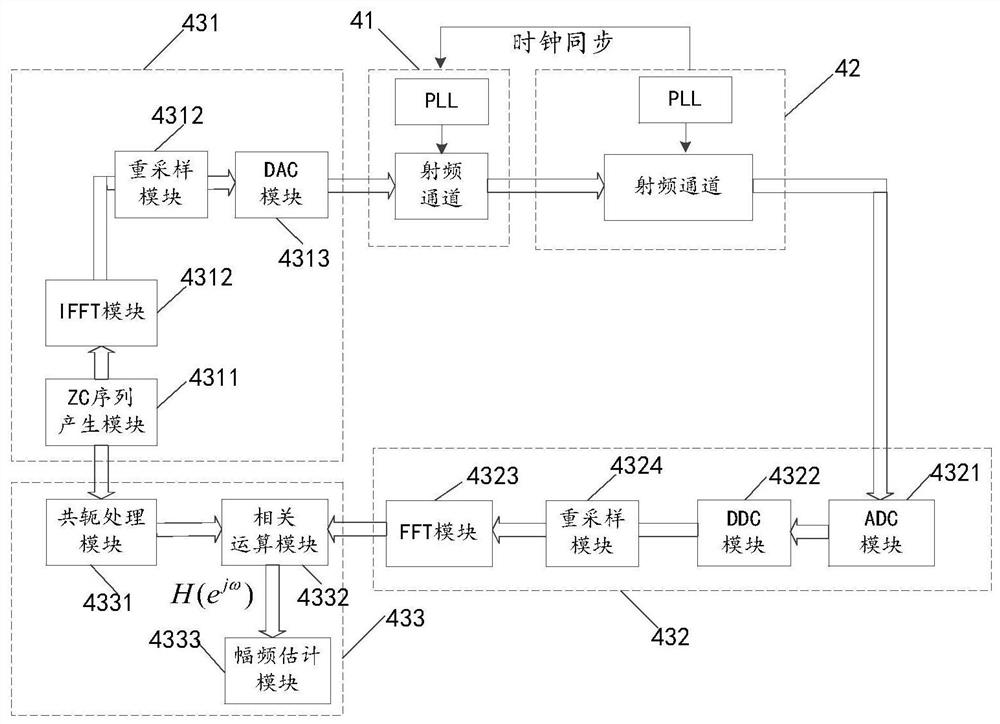
[0073] Step S100, the second processing is performed on the output signal generated by the radio frequency channel of the receiver 42 in response to the transmission signal to obtain a receiving sequence; wherein the transmission signal is the signal obtained after the first processing by the radio frequency channel of the transmitter 41 in response to the ZC sequence And produced. In a specific example, see Figure 5 , step S100 may include steps S110-S160, which are respectively described as follows.

[0074] Next, steps S110-S130 will be used to describe in detail the process of generating a transmission signal by the radio frequency channel of the transmitter in response to the signal obtained after the first processing of the ZC sequence.

[0075] St...


PUM


Abstract

The invention relates to a broadband frequency response measuring method and a broadband frequency response measuring device. The measuring method comprises the steps of carrying out second processingon an output signal generated by a radio frequency channel of a receiver in response to a transmitting signal to obtain a receiving sequence, and the transmitting signal being generated by a radio frequency channel of a transmitter in response to a signal obtained by carrying out first processing on a ZC sequence; and calculating to obtain a frequency response measurement result of the radio frequency channel to be measured according to the ZC sequence and the receiving sequence. The ZC sequence is applied to the broadband frequency response measurement process of the transmitter or the receiver; the limitation that frequency sweeping is carried out by utilizing a single-tone signal in the past is overcome; a new measurement scheme is provided, the amplitude-frequency characteristics in the frequency response of the to-be-measured radio frequency channel can be obtained, the phase-frequency characteristics in the frequency response of the to-be-measured radio frequency channel can also be obtained, and correction and compensation of the to-be-measured channel according to the obtained amplitude-frequency characteristics and phase-frequency characteristics in the later period are facilitated.

Description

technical field [0001] The invention relates to a signal test and measurement technology, in particular to a wideband frequency response measurement method and a measurement device thereof. Background technique [0002] In the field of test and measurement, signal generators (including arbitrary waveform generators, radio frequency signal sources, vector signal generators, etc.) For waveform-shaped signals, the spectrum analyzer is used to receive and measure various signals, for example, it can measure the power (amplitude), frequency, phase, bandwidth, etc. of the signal, and even perform various modulation and demodulation analysis on the signal. These instruments and equipment often include analog signal channels and digital signal channels, and there are a large number of analog devices in the analog signal channels, such as amplifiers, filters, mixers, etc., the amplitude-frequency of the analog circuit composed of these analog devices The response curve (referred to ...

Claims


Application Information

Patent Timeline
IPC IPC(8): H04B17/00H04B17/15H04B17/29
CPCH04B17/0085H04B17/15H04B17/29
Inventor 王永添郑翠翠马兴望罗森
Owner SHENZHEN CITY SIGLENT TECH
Learn More