[0018] The technical solutions in the embodiments of the present invention will be clearly and completely described below with reference to the accompanying drawings in the embodiments of the present invention. Obviously, the described embodiments are only a part of the embodiments of the present invention, but not all of the embodiments. Based on the embodiments of the present invention, all other embodiments obtained by those of ordinary skill in the art without creative efforts shall fall within the protection scope of the present invention.
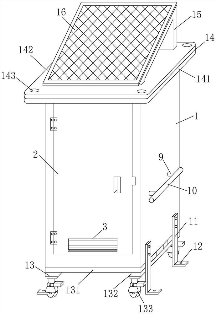
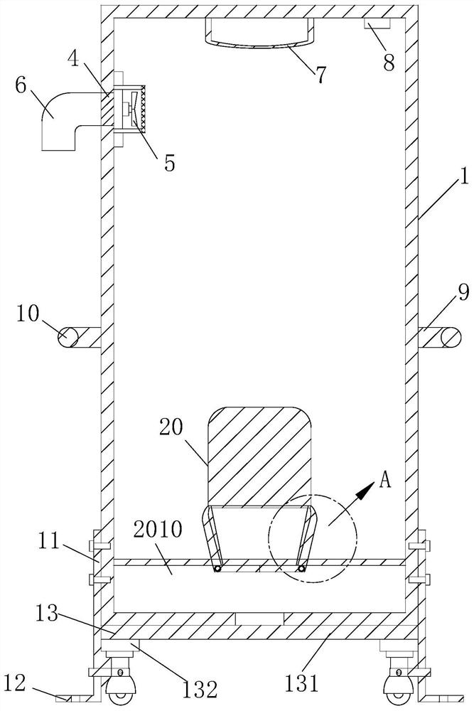
[0019] see Figure 1-4 As shown, the present invention provides an urban municipal waterless toilet system, comprising a waterless toilet body 1, the bottom end of the waterless toilet body 1 is fixedly provided with a moving mechanism 13, and the front of the waterless toilet body 1 is hinged with a safety door 2 , the bottom of the front of the safety door 2 is fixed with shutters 3, the bottoms of the two sides of the waterless toilet body 1 are respectively fixed with two vertical plates 11 by bolts, and the bottom ends of the four vertical plates 11 are fixed with limit plates 12. The tops of the four limiting plates 12 are all provided with limiting holes, the top of one side of the waterless toilet body 1 is provided with an air exhaust port 4, one side of the air exhaust port 4 is fixedly provided with an air exhaust pipe 6, and one side of the waterless toilet body 1 is provided with an air exhaust pipe 6. The interior of the top is fixedly provided with a suction fan 5 corresponding to the position of the air suction port 4, the inner wall of the top middle of the waterless toilet body 1 is fixedly provided with a lighting lamp 7, and the inner wall of the top side of the waterless toilet body 1 is fixedly provided with an induction switch 8. , the top of the waterless toilet body 1 is fixedly connected with the bottom end of the hoisting mechanism 14, the two sides of the top of the hoisting mechanism 14 are respectively fixedly connected with the two sides of the bottom end of the bracket 15, the top of the bracket 15 is fixedly provided with a solar panel 16, and the hoisting mechanism The middle part of the top of 14 is fixedly provided with a casing 17, the interior of the casing 17 is respectively fixed with a battery 18 and a timer 19, the solar panel 16 is electromagnetically connected with the battery 18, the exhaust fan 5 is electrically connected with the timer 19, and the waterless toilet body The toilet 20 is installed in the interior of 1 .
[0020] Specifically, the toilet 20 includes a base 204 fixed on the toilet body 1 through a support plate 207 , the base 204 is movably connected with a flip 201 through a rotating shaft 202 , and two ends of the rotating shaft 202 are connected with pull ropes 203 , and the pull ropes 203 pass through the base 204 The side wall is connected to the rotating plate 205, the rotating plate 205 is rotatably connected to the fixing pin 206 through the rotating sleeve 208, the fixing pin 206 is installed at the bottom of the base 204, and the inside of the rotating sleeve 208 is provided with a torsion spring sleeved on the fixing pin 206 209, a storage cavity 2010 is provided at the bottom of the rotating plate 205 and the supporting plate 207. By turning the flip cover 201, the pull rope 203 can be driven to shrink, and the pull rope 203 shrinks and pulls the turn plate 205 to rotate upward, so that the turn board 205 seals the base 204. When the flip cover 201 is turned down, the flip cover 201 is covered on the base 204, the turning plate 205 will be turned downward so that the excrement enters the interior of the storage cavity 2010 for storage, and finally the excrement in the storage cavity 2010 can be uniformly processed.
[0021] Specifically, the moving mechanism 13 includes several cross beams 131, two longitudinal beams 132 and four universal wheels 133. The tops of the several cross beams 131 are fixedly connected to the bottom end of the waterless toilet body 1, and the bottoms of the several cross beams 131 are fixedly connected. The ends are respectively fixedly connected with the top ends of the two longitudinal beams 132, and the bottom ends of the two longitudinal beams 132 are respectively fixed with universal wheels 133. The direction wheel 133 is convenient for moving the waterless toilet body 1; the hoisting mechanism 14 includes a hoisting plate 141, a waterproof plate 142 and four hoisting holes 143, the bottom end of the hoisting plate 141 is fixedly connected with the top of the waterless toilet body 1, and the top of the hoisting plate 141 is fixedly connected. There are hoisting holes 143 at the four corners of the hoisting plate 141 , the top of the hoisting plate 141 is fixedly provided with a waterproof plate 142 , the two sides of the top of the waterproof plate 142 are fixedly connected to the two sides of the bottom end of the bracket 15 respectively, and the middle of the top of the waterproof plate 142 is fixedly installed. There is a casing 17, and it is convenient to hoist the waterless toilet body 1 through the four hoisting holes 143 and load it on the vehicle. By setting the waterproof plate 142, the waterproof performance of the hoisting plate 141 is improved; Two connecting rods 9 are fixed in the middle, and one end of the four connecting rods 9 is fixedly connected with the two sides of the two handrails 10 respectively, and the waterless toilet body 1 is easily pushed through the handrails 10; A protective cover, an operation door is hinged on one side of the outer casing 17, through which the injury to people caused by the rotation of the exhaust fan 5 can be avoided, and the battery 18 and the timer 19 can be easily installed and disassembled by opening the operation door; The battery 18 is electrically connected, and a timer switch is fixed on the surface of the timer 19. The timer 19 is electrically connected to the power supply through the timer switch, and the induction switch 8 and the timer switch are convenient to control the work of the lighting lamp 7 and the timer respectively. 19 jobs.
[0022]In specific use, the present invention is an urban municipal waterless toilet system. The waterless toilet body 1 can be moved by pushing the handrail 10. When the waterless toilet body 1 needs to be loaded and transported, the lifting plate 141 can be used. The four hoisting holes 143 of the waterless toilet body 1 are hoisted to the vehicle, and after transporting to the designated location, the four vertical plates 11 are respectively fixed on both sides of the waterless toilet body 1 by bolts, and then the limit holes are fixed through the limit holes. The panel 12 is fixed on the ground and fixed to the waterless toilet body 1. The solar panel 16 can convert light energy into electrical energy and store it in the storage battery 18. When people open the safety door 2, the induction switch 8, which can be G18D107, senses the human body. Then turn on the lighting lamp 7 to illuminate the interior of the waterless toilet body 1. The working time and sleep time of the suction fan 5 can be set for the timer 19 of the KG316T through the model, which can prevent the suction fan 5 from working all the time, causing the suction fan 5 to be in a working state. The fan 5 is damaged. When the exhaust fan 5 is working, the air inside the waterless toilet body 1 is pumped to the outside to achieve the effect of deodorization. The outside air reaches the interior of the waterless toilet body 1 through the shutter 3, and keeps the waterless toilet body 1 The circulation of internal air. Flip the flip cover 201, the flip cover drives the rotating shaft 202 to rotate, the rotating shaft 202 can drive the pull rope 203 to shrink, the pull rope 203 shrinks and pulls the rotating plate 205 to rotate upward, so that the rotating plate 205 seals the base 204, when the flip 201 is turned down, The flip cover 201 is covered on the base 204, and the turning plate 205 is turned downward so that the excrement enters the storage cavity 2010 for storage, and finally the excrement in the storage cavity 2010 can be uniformly processed.
[0023] In the description of the present invention, it should be understood that the indicated orientation or positional relationship is based on the orientation or positional relationship shown in the accompanying drawings, which is only for the convenience of describing the present invention and simplifying the description, rather than indicating or implying the indicated device. Or elements must have a particular orientation, be constructed and operate in a particular orientation, and therefore should not be construed as limiting the invention.
[0024] In the present invention, unless otherwise expressly specified and limited, for example, it may be a fixed connection, a detachable connection, or an integrated; it may be a mechanical connection or an electrical connection; it may be a direct connection or a The indirect connection through an intermediate medium may be the internal communication of two elements or the interaction relationship between the two elements. Unless otherwise clearly defined, those of ordinary skill in the art can understand the above terms in the present invention according to specific circumstances. specific meaning in .
[0025] Although embodiments of the present invention have been shown and described, it will be understood by those skilled in the art that various changes, modifications, and substitutions can be made in these embodiments without departing from the principle and spirit of the invention and modifications, the scope of the present invention is defined by the appended claims and their equivalents.