
Pipeline in-vivo fixing device and using method thereof

A technology for fixing devices and pipes, applied in the direction of catheters, hollow probes, etc., can solve the problems of balloon prolapse, weak structure, uneven force, etc.

Pending Publication Date: 2020-10-30
山东安可医疗器械有限公司
View PDF0 Cites 0 Cited by
  • Summary
  • Abstract
  • Description
  • Claims
  • Application Information

AI Technical Summary

Problems solved by technology

[0002] Ostomy tubes and drainage tubes are widely used in clinical surgery, including enterostomy tubes, urethral fistula tubes, etc., which can lead the body's excrement out of the body. Waist belt, etc., fix the ostomy tube and drainage tube inside and outside the body, but this fixing method makes the patient's movement more inconvenient, and it is easy to drop, resulting in the need to re-fix the ostomy tube, which brings more inconvenience to the patient. big trouble
Most of the existing fixed pieces in the body of the pipeline are flat fixed pieces. When using them, foreign body forceps, endoscopes, steel wires and other instruments must be borrowed from the ostomy and drainage ports, and pulled out from the inside out. They need to be replaced or taken out. Methods, such as gastrostomy, need to be used from the mouth, steel wires, lead wires enter the esophagus, and then fixed in the stomach, take out or replace, gastroscope, foreign body forceps enter the esophagus from the mouth to take out the stomach, it is very inconvenient to operate; For the front end of the balloon type, the part where the balloon is installed in the pipeline is mostly protruding, and it is inconvenient to insert and pull out the narrow part. The balloon protrudes from the ostomy or socket, and the balloon becomes thinner after inflation and water filling. The structure is not strong and is easily corroded and damaged by the digestive juice or tissue fluid in the body. The liquid or gas in the balloon enters the human body, causing medical accidents

Method used


Image

  • Pipeline in-vivo fixing device and using method thereof
  • Pipeline in-vivo fixing device and using method thereof

Examples


Embodiment Construction

[0025] The technical solutions in the embodiments of the present invention will be clearly and completely described below in conjunction with the accompanying drawings in the embodiments of the present invention

[0026] Description, it should be understood that the preferred embodiments described here are only used to illustrate and explain the present invention, not to limit the present invention.

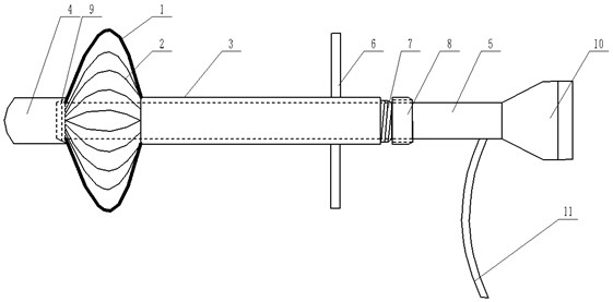
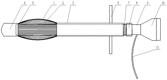
[0027] Referring to the accompanying drawings of the specification, a pipeline body fixing device includes an outer tube 3 and an inner tube 5, and the outer walls of the outer tube 3 and the inner tube 5 are provided with scale lines, and the scale lines on the outer wall of the outer tube 3 are convenient for viewing when the device is inserted into human organs position, the outer wall of the inner tube 5 can determine the size of the foldable elastic skeleton 2; The length is longer than the outer tube 3, the front end of the inner tube 5 and the front end of the outer tube 3...


PUM


Abstract

The invention discloses a pipeline in-vivo fixing device and a using method thereof. The device comprises an outer pipe and an inner pipe, the inner pipe is sleeved with the outer pipe, the front endof the inner pipe and the front end of the outer pipe are connected with a plurality of foldable elastic frameworks, when the distance between the front end of the inner pipe and the front end of theouter pipe is the longest, the foldable elastic frameworks are tightly attached to the inner pipe; when the front end of the inner pipe is close to the front end of the outer pipe, the foldable elastic frameworks are unfolded outwards to form a lantern shape; a hollow elastic fixing disc is arranged outside the foldable elastic frameworks. Through the structural design, the operation is simpler and more convenient, and the pain of a patient is relieved; the lantern-shaped hollow elastic fixing disc is opened through the foldable elastic frameworks, water filling and air filling are not needed,the structure is firm and durable, and the risk of medical accidents is reduced.

Description

technical field [0001] The invention relates to the field of medical devices, in particular to a pipeline internal fixation device and a use method thereof. Background technique [0002] Ostomy tubes and drainage tubes are widely used in clinical surgery, including enterostomy tubes, urethral fistula tubes, etc., which can lead the body's excrement out of the body. Waist belt, etc., fix the ostomy tube and drainage tube inside and outside the body, but this fixing method makes the patient's movement more inconvenient, and it is easy to drop, resulting in the need to re-fix the ostomy tube, which brings more inconvenience to the patient. Big trouble. Most of the existing fixed pieces in the body of the pipeline are flat fixed pieces. When using them, foreign body forceps, endoscopes, steel wires and other instruments must be borrowed from the ostomy and drainage ports, and pulled out from the inside out. They need to be replaced or taken out. Methods, such as gastrostomy, n...

Claims


Application Information

Patent Timeline
Patent Type & Authority Applications(China)
IPC IPC(8): A61M25/04A61M25/14
CPCA61M25/003A61M25/04A61M2025/0008
Inventor 齐卫东
Owner 山东安可医疗器械有限公司
Learn More