Water segregator

A water separator and tail part technology, which is applied in the field of water separators with new structures, can solve problems such as blockage of flow channels, unfavorable integration applicability of water separator layout, system volume power density, and impact on fuel cell performance.

Active Publication Date: 2020-10-30
SHANGHAI HYDROGEN PROPULSION TECH CO LTD
View PDF19 Cites 0 Cited by
  • Summary
  • Abstract
  • Description
  • Claims
  • Application Information

AI Technical Summary

Problems solved by technology

[0005] For the first type of device, considering the water separation efficiency, the gas-liquid mixture needs to form a sufficiently large vortex and centrifugal force, so the size of the water separator is relatively fixed and the volume is large, which is not conducive to improving the layout and integration applicability of the water separation

Method used


Image

  • Water segregator
  • Water segregator
  • Water segregator

Examples


no. 1 Embodiment

[0071] The first specific embodiment of the present invention provides a water separator.

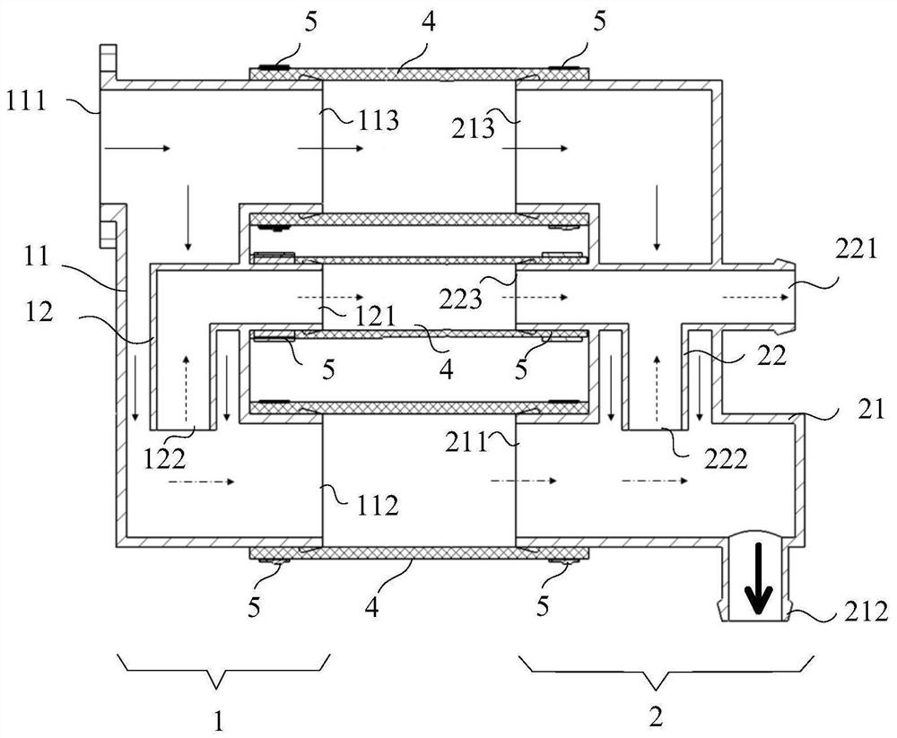
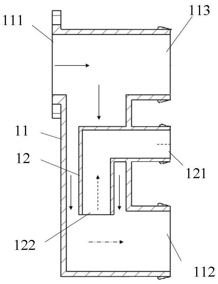
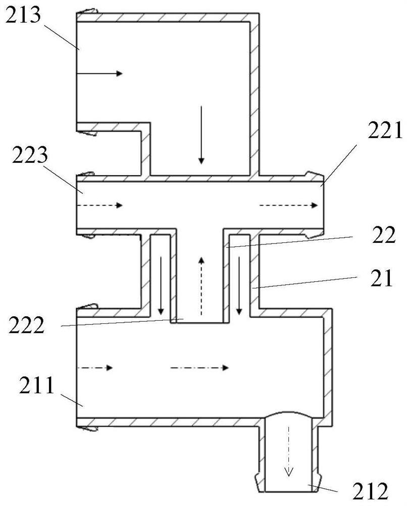
[0072] see Figure 1 to Figure 3 , figure 1 A cross-sectional view of the water separator provided for the first specific embodiment of the present invention; figure 2 A sectional view of the first water diversion section provided for the first specific embodiment of the present invention; image 3 A cross-sectional view of the water diversion section at the tail provided for the first specific embodiment of the present invention. Wherein, the dotted line arrows in the figure indicate the drainage direction of the separated gas, the solid line arrows indicate the flow direction of the mixed fluid, and the dotted line arrows indicate the flow direction of the separated liquid.

[0073] The water separator provided by the first specific embodiment of the present invention includes a first water diversion section 1 and a tail water diversion section 2, wherein:

[0074] The first part...

no. 2 Embodiment

[0094] The second specific embodiment of the present invention provides a water separator.

[0095] see Figure 4 to Figure 6 , Figure 4 A schematic diagram of the overall structure of the water separator provided for the second specific embodiment of the present invention; Figure 5 A cross-sectional view of the water separator provided for the second specific embodiment of the present invention; Figure 6 A cross-sectional view of the middle water dividing section provided for the second specific embodiment of the present invention.

[0096] The only difference between the water separator provided by the second specific embodiment of the present invention and the water separator provided by the first specific embodiment of the present invention is that the water separator provided by the second specific embodiment of the present invention is different from that provided by the first specific embodiment. On the basis of the water separator, an intermediate water diversion...

no. 3 Embodiment

[0109] The third specific embodiment of the present invention provides a water separator.

[0110] The difference between the water distributor provided by the third specific embodiment of the present invention and the water distributor provided by the second specific embodiment of the present invention is only that a plurality of intermediate water diversion sections are arranged in parallel in sequence, thus, the second specific embodiment provides On the basis of the water separator, the length of the pipeline is extended to realize more diversion and reverse drainage. For details, see Figure 5 and Figure 6 , the water separator provided by the third specific embodiment of the present invention, in Figure 5 On the basis of this, multiple intermediate water diversion sections 3 are arranged in parallel.

[0111] Specifically, in the water separator provided by the third specific embodiment of the present invention:

[0112] The two adjacent middle water dividing secti...


PUM


Abstract

The invention discloses a water segregator. According to the water segregator, gas separated out of a head main flow pipe can be reversely drained and output through a head drainage pipe, and gas separated from a tail main flow pipe can be reversely drained and output through a tail drainage pipe, so liquid drops and gas in a gas-liquid mixture are separated multiple times by utilizing inertia force, and good water segregation efficiency is guaranteed. Therefore, the water segregator of the invention does not need structures such as a centrifugal mechanism, a filter element or a corrugated plate and can realize water segregation only through a nested pipeline structure, and therefore, the technical problems of large size, large flow resistance and the like of devices in the prior art can be solved. Furthermore, the water segregator can be configured to be of a multi-stage flexible structure, so the applicability of the water segregator is improved.

Description

technical field [0001] The invention relates to the technical field of fuel cells, in particular to a water separator with a new structure. Background technique [0002] The existing water separators for fuel cells can be divided into two categories based on basic principles: [0003] (1) Centrifugal force is used to separate liquid droplets, and guide vanes, or baffle structures, or spiral flow channels are used in the water separator to induce the gas-liquid mixture to rotate at high speed, and the liquid droplets are thrown to the water separator under the action of centrifugal force The inner wall of the device and flow down to achieve the purpose of separation from the gas; [0004] (2) Utilize the droplet adhesion, adopt filter element or corrugated plate and other structures to increase the contact area between the droplet and the surrounding wall surface, so that the droplet adheres to the wall surface and achieves the purpose of separating from the gas. [0005] F...

Claims


Application Information

Patent Timeline
IPC IPC(8): B01D45/04
CPCB01D45/04
Inventor 尚鹏飞李秋红贾勇琪侯中军蔡俊王克勇
Owner SHANGHAI HYDROGEN PROPULSION TECH CO LTD
Why Eureka
Try Eureka