Eureka AIR delivers breakthrough ideas for toughest innovation challenges, trusted by R&D personnel around the world.

Sand mixer

A sand mixer and sand mixing technology, applied in the cleaning/processing machinery of casting mold materials, casting molding equipment, metal processing equipment, etc., can solve the problems of long downtime and low efficiency of sand mixing

Active Publication Date: 2020-10-30
南京龙宁机床装备有限公司
View PDF6 Cites 0 Cited by
  • Summary
  • Abstract
  • Description
  • Claims
  • Application Information

AI Technical Summary

Problems solved by technology

[0003] The purpose of the present invention is to provide a sand mixer, which solves the technical defect of low sand mixing efficiency due to the long shutdown time required to discharge sand in sand mixing in the prior art

Method used


Image

  • Sand mixer
  • Sand mixer
  • Sand mixer

Examples


Embodiment Construction

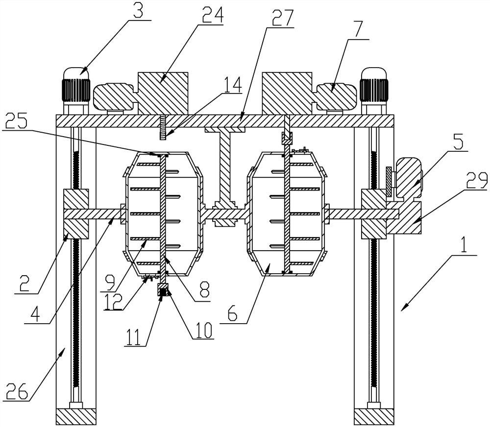
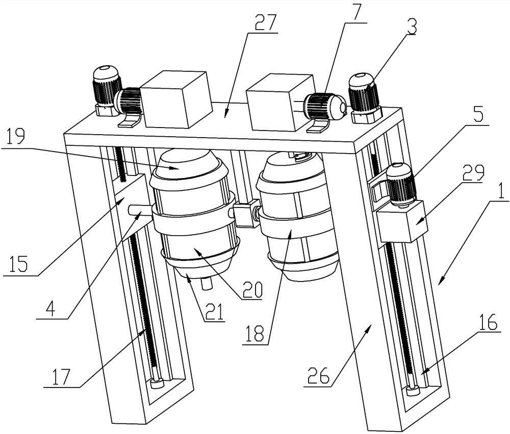
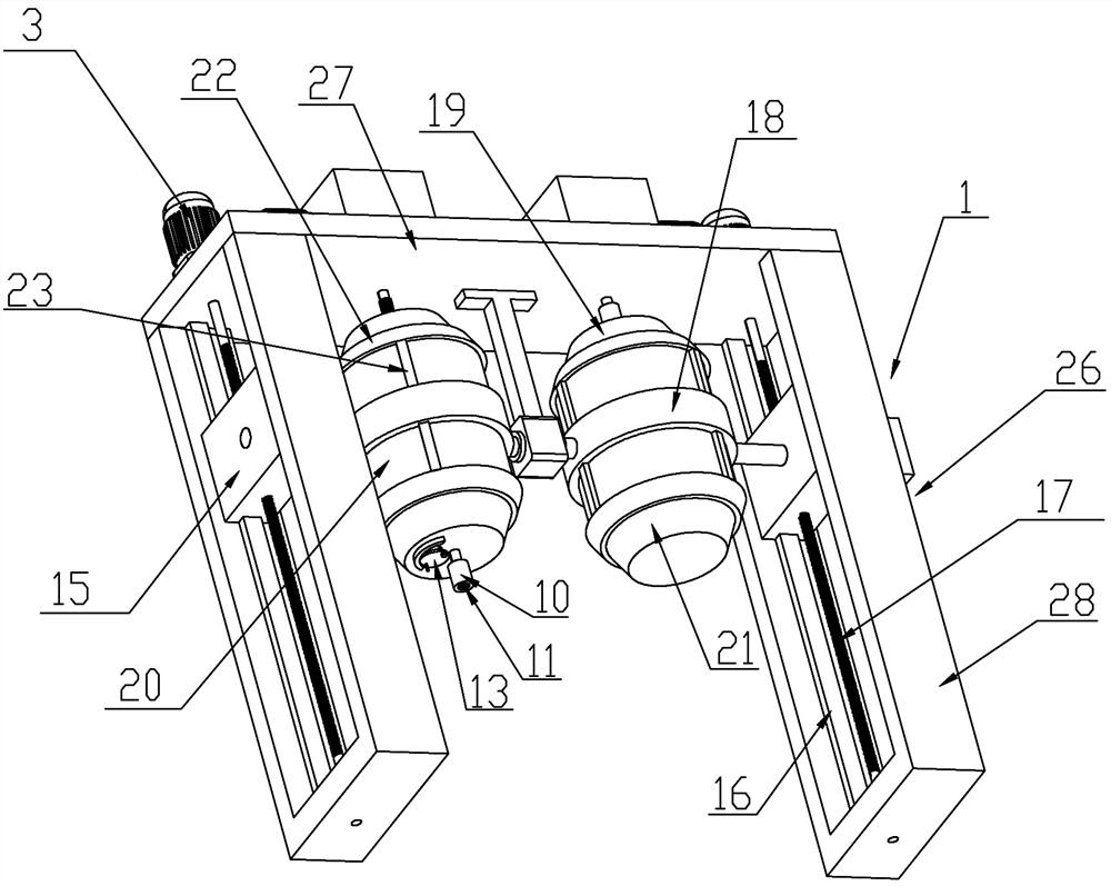
[0019] The specific embodiments of the present invention will be further described below in conjunction with the accompanying drawings.

[0020] Such as Figure 1 to Figure 3 The sand mixer shown includes a frame 1, a lifting frame 2, a lifting motor 3, a turning frame 4, a turning motor 5, two sand mixing barrels 6 and two sand mixing motors 7, and the lifting frame 2 is arranged on On the frame 1 and constitute a vertical movement pair with the frame 1, the lifting motor 3 drives the lifting frame 2 to move vertically on the frame 1, and the turning motor 5 is installed on the lifting frame 2, and the turning frame 4 Rotation is set on the lift frame 2 and is turned over by the turning motor 5 relative to the lift frame 2. The two sand mixing buckets 6 are all arranged on the turn frame 4 and turn over with the turn over of the turn frame 4. A stirring shaft 8 is arranged in the sand barrel 6, and a stirring blade 9 is arranged on the stirring shaft 8, and one end of the st...


PUM


Abstract

The invention discloses a sand mixer. The sand mixer comprises a rack, a lifting frame, a lifting motor, a turning frame, a turning motor, two sand mixing barrels and two sand mixing motors, the lifting frame is arranged on the rack, the turning motor is installed on the lifting frame, the turning frame is rotationally arranged on the lifting frame, the two sand mixing barrels are arranged on theturning frame, stirring shafts are arranged in the sand mixing barrels, stirring blades are arranged on the stirring shafts, one ends of the stirring shafts extend out of the sand mixing barrels fromone ends of the sand mixing barrels, connecting pieces are arranged at the ends, extending out of the sand mixing barrels, of the stirring shafts, internal splines are arranged on the connecting pieces, sand inlet and outlet ports of the two sand mixing barrels are formed in the ends, away from each other, of the two sand mixing barrels correspondingly, the sand mixing motors are arranged at the top of the rack, and external splines capable of being matched with the internal splines on the connecting pieces are arranged at the ends of output shafts of the sand mixing motors. According to the sand mixer, the two sand mixing barrels are arranged, when one sand mixing barrel mixes sand, the other sand mixing barrel discharges the sand outwards, so that the downtime for discharging the sand isshortened, and the sand mixing efficiency of the sand mixer is improved.

Description

technical field [0001] The invention relates to a sand mixer, which belongs to the technical field of sand box casting. Background technique [0002] In the field of sand box casting, the sand mixer is an indispensable tool. It is a machine that uniforms the foundry sand, binder, additive, water, etc. and makes it into molding sand or core sand with certain properties. The existing sand mixer comprises a sand mixing cylinder, a motor, a stirring shaft, a stirring paddle, etc., and the motor drives the stirring shaft and the stirring paddle to rotate, so as to stir and mix the sand in the sand mixing cylinder evenly. When the existing sand mixer is unloading, the sand in the sand mixing cylinder is discharged from the shutdown, and then new sand is added to the sand mixing cylinder. After the above actions are completed, the motor is turned on to continue sand mixing. The existing sand mixer Long downtime and low sand mixing efficiency. Contents of the invention [0003] ...

Claims


Application Information

Patent Timeline
Patent Type & Authority Applications(China)
IPC IPC(8): B22C5/04
CPCB22C5/045
Inventor 赵德智赵善平吕锡震施小福许建军高雪平陈红亮
Owner 南京龙宁机床装备有限公司
Why Eureka
Eureka Blog
Learn More