
Clamping spring assembling and detecting technology and device

A technology of assembly detection and circlip, applied in metal processing, manufacturing tools, metal processing equipment, etc., can solve the problems of high error rate, inaccurate detection, inaccurate manual assembly and placement, etc., so as to reduce the cycle time of the station and improve the work efficiency Efficiency and the effect of reducing the workload of manual operations

Inactive Publication Date: 2020-10-30
SHENGRUI TRANSMISSION
View PDF5 Cites 2 Cited by
  • Summary
  • Abstract
  • Description
  • Claims
  • Application Information

AI Technical Summary

Problems solved by technology

[0003] In the prior art, the circlip is manually placed on the circlip shaft, and whether the circlip is assembled into the circlip shaft groove is observed with the naked eye. The inventor finds that the prior art has the following disadvantages in the process of realizing the present invention: 1. Manual assembly Inaccurate placement, high error rate; 2. Visually check whether the circlip is placed in place, imprecise detection, high error rate

Method used


Image

  • Clamping spring assembling and detecting technology and device
  • Clamping spring assembling and detecting technology and device
  • Clamping spring assembling and detecting technology and device

Examples


Embodiment 1

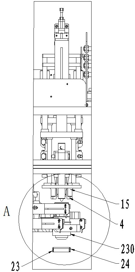
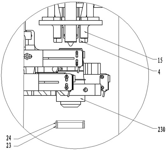
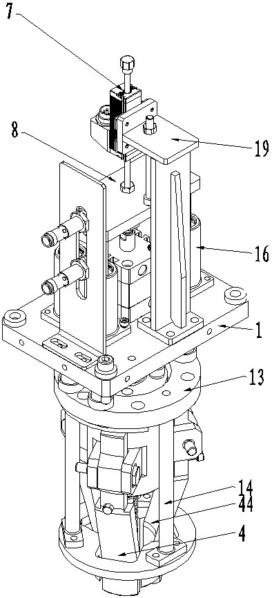
[0034] Example 1, such as Figure 1-5 As shown, a circlip assembly detection process, including

[0035] Prepare materials, manually put the circlips to be assembled into the silo.

[0036] Blowing, manual jump ring is taken out from feed bin, is placed on the guide block 230.

[0037] The guide block is positioned, the jaws clamp the guide block 230 and move downward until the bottom surface of the guide block 230 moves to the end surface of the snap ring shaft 23,

[0038] The bottom end of the guide block 230 matches the inner diameter of the snap ring shaft 23;

[0039] After the guide block 230 is fixed, the controller sends a command, and the jaws release the guide block 230 .

[0040] The outer diameter of guide block 230 is identical with the outer diameter of jump ring shaft 23;

[0041] Press the circlip, the first cylinder (not shown in the figure) drives the first connecting plate 1 to move vertically downward, the entire press-fit mechanism moves vertically do...


PUM


Abstract

The invention discloses a clamping spring assembling and detecting technology. The technology comprises the steps that a clamping spring is placed on a guide block; the guide block is located in a clamping spring shaft; under guiding of the guide block, a pressing head of a press-fitting mechanism presses the clamping spring into a clamping spring shaft groove, the pressing head of the press-fitting mechanism carries out press fitting on the clamping spring along the conical guide face of the guide block, the conical guide face struts the diameter of the clamping spring, and the clamping spring enters the clamping spring shaft groove; and a detecting mechanism detects whether the clamping spring is installed in place or not. A device used for achieving the technology comprises a clamping spring press-fitting and detecting device. The clamping spring press-fitting and detecting device comprises the press-fitting mechanism and a locating and guiding device. The press-fitting mechanism comprises the pressing head. The pressing head comprises a connecting end and a pressing head end. An included angle alpha is arranged between the connecting end and the pressing head end. The side faceof the pressing head end is provided with a first guide face. The locating and guiding device comprises the guide block. The top end of the guide block is provided with the conical guide face matchedwith the first guide face. According to the technology, press-fitting and detecting automation can be achieved in the clamping spring assembling process.

Description

technical field [0001] The invention belongs to the technical field of circlip assembly, and in particular relates to a circlip assembly detection process and device. Background technique [0002] As a fastener, the circlip is also called a retaining ring or a buckle. The circlip is mainly used in the shaft groove or hole groove of the machine or equipment, and plays a role in preventing the axial movement of the parts on the shaft or the hole. [0003] In the prior art, the circlip is manually placed on the circlip shaft, and whether the circlip is assembled into the circlip shaft groove is observed with the naked eye. The inventor finds that the prior art has the following disadvantages in the process of realizing the present invention: 1. Manual assembly The placement is not accurate, and the error rate is high; 2. Check with the naked eye whether the circlip is placed in place, the detection is not accurate, and the error rate is high. Contents of the invention [000...

Claims


Application Information

Patent Timeline
IPC IPC(8): B23P19/04
CPCB23P19/04
Inventor 王鲁齐杰李健张启飞张建坤
Owner SHENGRUI TRANSMISSION
Learn More