Terminal positioning screw assembling device

A technology for positioning screws and assembling devices, which is applied in metal processing, metal processing equipment, manufacturing tools, etc., and can solve the problems of low terminal screwing efficiency and terminal screwing.

Active Publication Date: 2020-10-30
安徽奇盟光电科技有限公司
View PDF5 Cites 0 Cited by
  • Summary
  • Abstract
  • Description
  • Claims
  • Application Information

AI Technical Summary

Problems solved by technology

[0005] In order to overcome the shortcomings that the existing terminal screw loading detection device cannot automatically screw the terminal, and the efficiency of terminal screwing is low, the technical problem of the pre

Method used


Image

  • Terminal positioning screw assembling device
  • Terminal positioning screw assembling device
  • Terminal positioning screw assembling device

Examples


Embodiment 1

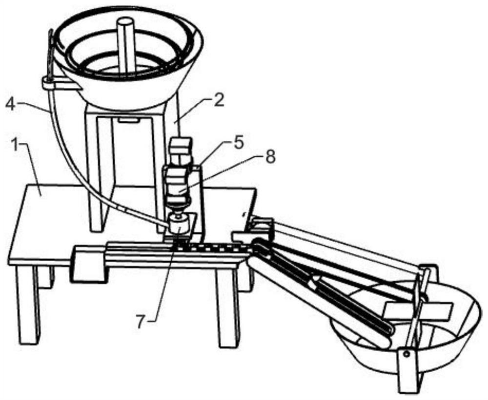
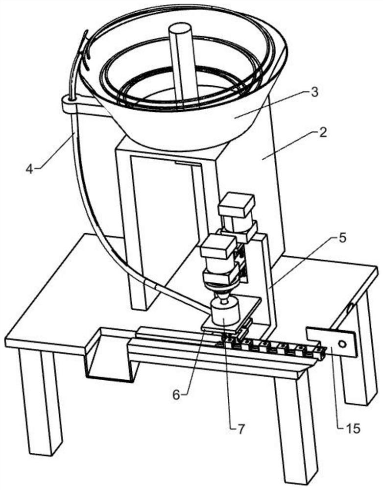
[0029] A terminal set screw assembly device, such as figure 1 and figure 2 As shown, it includes a workbench 1, a connecting frame 2, a vibrating material transfer plate 3, a conveying pipe 4, an L-shaped plate 5, a fixed plate 6, a clamping mechanism 7, a lifting mechanism 8 and a concave conveying frame 14, and the workbench 1 A connecting frame 2 is arranged on the connecting frame 2, a vibrating material transfer plate 3 is installed on the connecting frame 2, a delivery pipe 4 is fixed on the vibrating material transferring plate 3, an L-shaped plate 5 is arranged on the workbench 1 on the front side of the connecting frame 2, and the L-shaped plate 5 A fixed plate 6 is installed on the plate 5, and a clamping mechanism 7 is installed on the fixed plate 6. The clamping mechanism 7 cooperates with the delivery pipe 4. A lifting mechanism 8 is installed on the L-shaped plate 5. The lifting mechanism 8 cooperates with the clamping mechanism 7. , Concave delivery frame 14 i...

Embodiment 2

[0032] On the basis of Example 1, such as figure 1 and Figure 5 As shown, the clamping mechanism 7 includes a hollow barrel 71, claws 701 and a first spring 702, the hollow barrel 71 is embedded on the fixed plate 6, the hollow barrel 71 communicates with the conveying pipe 4, and the bottom of the hollow barrel 71 is rotatably connected with There are at least five claws 701 , and a first spring 702 is fixedly connected between the claws 701 and the hollow barrel 71 .

[0033] After the screw enters the conveying pipe 4 by vibrating the material transfer plate 3, the screw in the conveying pipe 4 slides rightward into the hollow barrel 71. Due to the cooperation of the claw 701 and the first spring 702, the screw can be prevented from moving forward. It will fall down and cause inconvenience to screw the terminals.

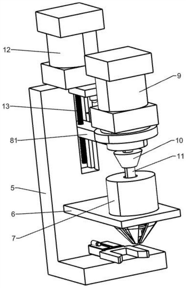
[0034] Such as figure 1 and image 3 As shown, the lifting mechanism 8 includes a horizontal plate 81, the first motor 9, a mounting block 10, a screwdriver...

Embodiment 3

[0039] On the basis of Example 2, such as figure 1 and Figure 6 Shown, also include the first pulley 17, the second pulley 171, belt 172, connecting plate 20, fixed frame 21, rotating shaft 22, conveying plate 23 and holding dish 24, the servomotor 16 of conveyer 161 rear sides The first pulley 17 is installed on the output shaft, the workbench 1 on the mounting plate 15 rear side is provided with a connecting plate 20, the connecting plate 20 is provided with a fixed mount 21, and the fixed mount 21 is rotatably provided with a rotating shaft 22, the rotating shaft 22 A second pulley 171 is installed on the top, a belt 172 is wound between the second pulley 171 and the first pulley 17, and at least four conveyor plates 23 are fixedly connected to the rotating shaft 22 on the front side of the second pulley 171. 21 is equipped with a holding tray 24, the delivery plate 23 is located in the holding tray 24, and the bottom of the conveyor 161 is located in the holding tray 24....


PUM


Abstract

The invention relates to a screw assembling device and particularly relates to a terminal positioning screw assembling device. The technical scheme is characterized in that the terminal positioning screw assembling device comprises a workbench and a clamping mechanism, wherein a connecting frame is mounted on the workbench; a vibratory material conveying disc is arranged on the connecting frame; aconveying pipe is mounted on the vibratory material conveying disc; an L-shaped plate is arranged on one side, close to the connecting frame, of the workbench; a fixed plate is mounted on the L-shaped plate; the clamping mechanism is arranged on the fixed plate and is matched with the conveying pipe. According to the terminal positioning screw assembling device, a conveying plate clockwise rotates to be matched with a conveyer; terminals can be conveyed to the conveyer; the terminals can be automatically fed, so that the terminal screwing efficiency can be improved; through an infrared sensor, an air cylinder can drive a limiting block to move forwards, fix and limit the terminals; and meanwhile, the infrared sensor is capable of starting a first motor and a speed reduction motor to operate, so that the terminals can be automatically screwed.

Description

technical field [0001] The invention relates to a screw assembly device, in particular to a terminal positioning screw assembly device. Background technique [0002] The terminal is the part that connects the battery to the external conductor; in electrical engineering, the terminal refers to the terminal, also known as the terminal. Copper, aluminum, iron, etc.; their main function is to transmit electrical signals or conduct electricity. [0003] In the prior art, for example, the patent with the publication number CN107262382A discloses a terminal screw loading detection device, which includes a terminal chute, a terminal pusher plate, a fixed plate, a horizontal pusher vibration motor, a longitudinal pusher vibration motor, a screw gun, and a detection gun , double-channel feeding barrel and pneumatic push rod; the terminal chute is used to carry terminals, the terminal push plate is arranged along the terminal chute, the lower part of the terminal push plate includes s...

Claims


Application Information

Patent Timeline
IPC IPC(8): B23P19/06
CPCB23P19/001B23P19/004B23P19/006B23P19/06
Inventor 陆则龙
Owner 安徽奇盟光电科技有限公司
Why Eureka
Try Eureka