Mixing device facilitating discharging for concrete processing

A mixing device and concrete technology, which is applied in the direction of mixing operation control device, unloading device, clay preparation device, etc., can solve the problems of waste of concrete resources, increase of worker's work intensity, concrete overflow hopper, etc.

Pending Publication Date: 2020-10-30
夏梅
View PDF5 Cites 21 Cited by
  • Summary
  • Abstract
  • Description
  • Claims
  • Application Information

AI Technical Summary

Problems solved by technology

[0003] At present, when the concrete mixing devices on the market are discharging, the workers usually need to manually open the valve to make the concrete flow out. However, if

Method used


Image

  • Mixing device facilitating discharging for concrete processing
  • Mixing device facilitating discharging for concrete processing
  • Mixing device facilitating discharging for concrete processing

Examples


Embodiment 1

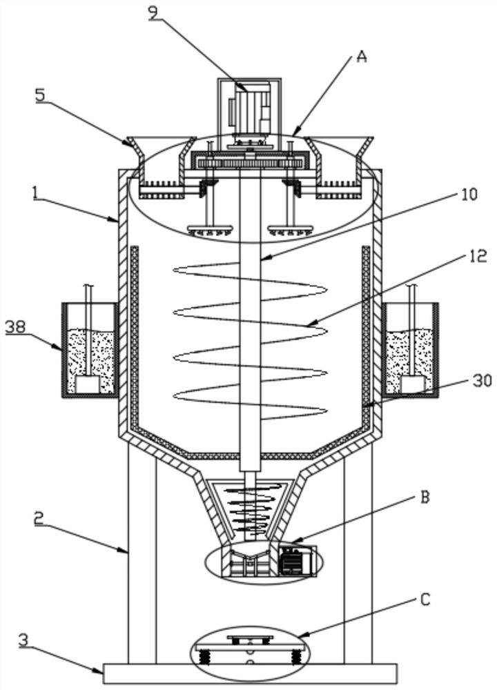
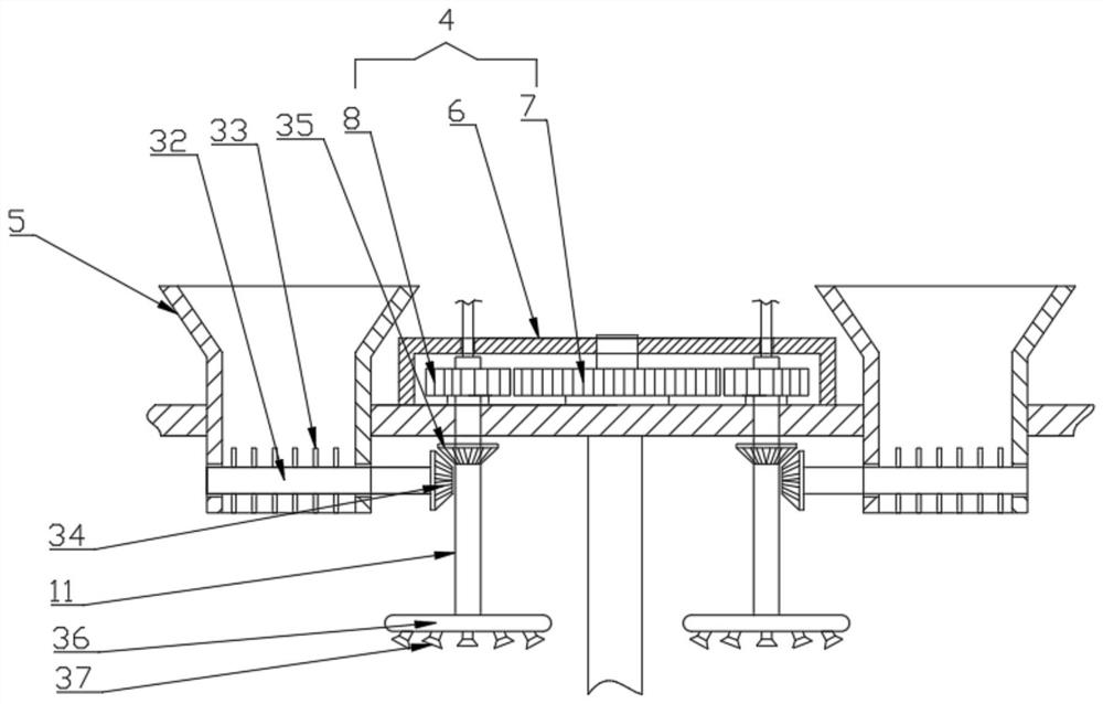
[0025] See Figure 1-5 , Including a mixing tank 1, the bottom of the mixing tank 1 is connected with a base 3 through a support column 2, the top of the mixing tank 1 is provided with a driving mechanism 4, the top of the mixing tank 1 is located on both sides of the driving mechanism 4 symmetrically provided The feed channel 5, and the bottom of the mixing tank 1 is provided with a discharge channel, the drive mechanism 4 includes a drive box 6, a first gear 7 and a second gear 8, the first gear 7 is arranged in the drive box 6 to rotate The first gear 7 is driven by the motor 9 provided on the top of the drive box 6. The second gear 8 is symmetrically arranged on both sides of the first gear 7, and the first gear 7 meshes with the second gear 8. The inside of the first gear 7 and the second gear 8 are respectively sleeved with a stirring rod 10 and a first rotating shaft 11. The stirring rod 10 and the first rotating shaft 11 both penetrate into the stirring tank 1, and the ...

Embodiment 2

[0031] This embodiment has been improved on the basis of embodiment 1, specifically:

[0032] The first rotating shaft 11 is a hollow shaft, and the bottom of the first rotating shaft 11 is provided with a shunt pipe 36. A number of atomizing nozzles 37 are evenly distributed under the shunt pipe 36. The side of the mixing tank 1 is symmetrically arranged The water tank 38 communicates with the top of the first rotating shaft 11 through a water pump and a water pipe. By setting an atomization nozzle 37, the water in the water tank 38 enters the first rotating shaft 11 through the water pump, and passes through the shunt pipe 36 to make the water Spraying from the atomizing nozzle 37, in conjunction with the rotation of the first rotating shaft 11, further expands the spraying area, thereby reducing the generation of dust during concrete mixing, and protecting the surrounding environment.

[0033] The working principle of the present invention is:

[0034] When in use, add concrete r...


PUM


Abstract

The invention discloses a mixing device facilitating discharging for concrete processing. The mixing device comprises a stirring tank, a driving mechanism is arranged at the top of the stirring tank,feeding channels are symmetrically formed in the positions, located on the two sides of the driving mechanism, of the top of the stirring tank, a discharging channel is formed in the bottom of the stirring tank, and a discharging mechanism is arranged in the discharging channel. According to the mixing device, through arranging the driving mechanism, when a motor rotates, a first gear is meshed with a second gear, so that a first rotating shaft rotates, a first bevel gear is meshed with a second bevel gear, a third rotating shaft rotates, and a guide rod is matched, so that a concrete raw material is smoothly guided into the stirring tank; and through arranging the discharging mechanism, a first annunciator and a second annunciator, quantitative discharging of the mixing device is achieved, the situation that concrete overflows out of a hopper due to misoperation of workers is avoided, resources are saved, and the working intensity of the workers is reduced.

Description

Technical field [0001] The invention relates to the technical field of building construction, in particular to a mixing device for concrete processing that is convenient for cutting. Background technique [0002] Concrete refers to a general term for engineering composite materials in which aggregates are cemented into a whole by cementitious materials. Generally speaking, the term concrete refers to cement concrete that uses cement as cementing material, sand and stone as aggregate; it is mixed with water (which may contain admixtures and admixtures) in a certain proportion and is mixed with cement concrete, also called ordinary Concrete, it is widely used in civil engineering. Concrete mixing is an operation method for mixing cement, lime, water and other materials and mixing them evenly. With the rapid development of the construction industry, the demand for concrete has greatly increased, and the mixing of concrete requires a special mixing device. [0003] When discharging t...

Claims


Application Information

Patent Timeline
IPC IPC(8): B28C5/16B28C7/16B28C7/14
CPCB28C5/16B28C7/0007B28C7/14B28C7/167
Inventor 夏梅
Owner 夏梅
Why Eureka
Try Eureka