A Flap Synchronous Drive Control Linkage Mechanism

A technology of synchronous drive and linkage mechanism, applied in the field of unmanned aerial vehicles, can solve the problem of inability to ensure that the flaps move synchronously at the same angle, and achieve the effect of improving energy utilization and overcoming tilt or left-right sway.

Active Publication Date: 2022-01-28
CHINA ELECTRONIC TECH GRP CORP NO 38 RES INST
View PDF9 Cites 0 Cited by
  • Summary
  • Abstract
  • Description
  • Claims
  • Application Information

AI Technical Summary

Problems solved by technology

However, this scheme uses the integrated flaperon to realize the functions of the original trailing edge flap lift and aileron roll control, but it cannot ensure that the flaps on both sides move synchronously and at the same angle.

Method used


Image

  • A Flap Synchronous Drive Control Linkage Mechanism
  • A Flap Synchronous Drive Control Linkage Mechanism
  • A Flap Synchronous Drive Control Linkage Mechanism

Examples


Embodiment 1

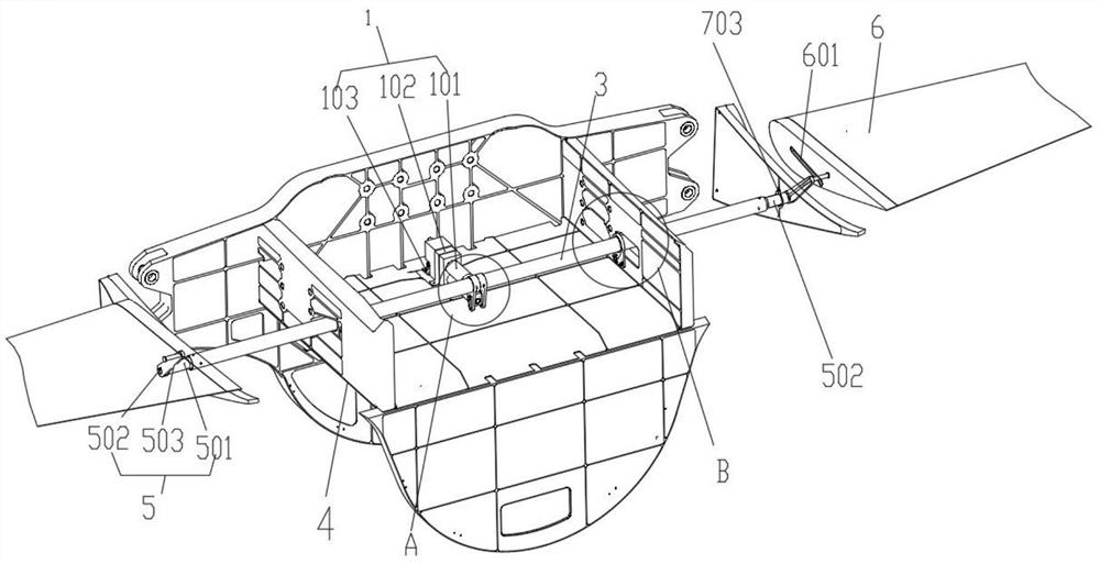
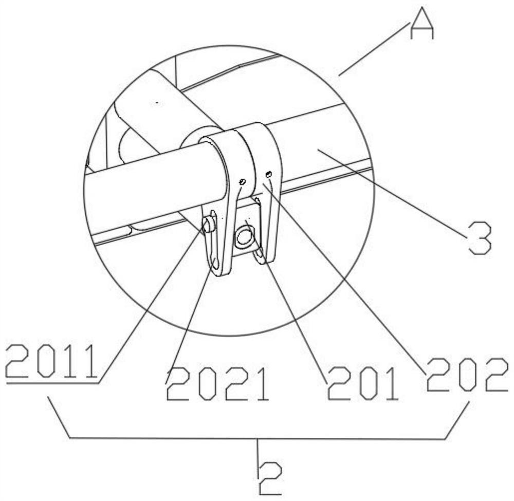
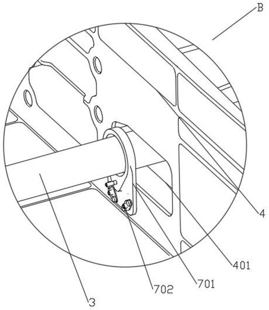
[0044] Such asfigure 1 , figure 2 and Figure 5 , figure 1 It is a three-dimensional schematic diagram of a flap synchronous drive control linkage mechanism provided by an embodiment of the present invention, figure 2 for figure 1 Schematic diagram of the enlarged structure of part A in the middle, Figure 5 A three-dimensional schematic diagram of the connection between the transmission rod and the crank structure in a flap synchronous drive control linkage mechanism provided by an embodiment of the present invention; the flap synchronous drive control linkage mechanism is arranged on the body 4, including:

[0045] A driving mechanism 1, the driving mechanism 1 is fixed to the rear side of the bottom of the body 4 by bolts;

[0046] A connector 2, the output shaft of the drive mechanism 1 is fixedly connected to the connector 2;

[0047] The transmission rod 3, the connecting piece 2 is sleeved at the middle position of the transmission rod 3, the driving mechanism 1 ...


PUM


Abstract

The invention relates to a flap synchronous drive control link mechanism, comprising: a driving mechanism is fixedly arranged at the bottom of the machine body near the rear side; an output shaft of the driving mechanism is fixedly connected with a connecting piece; the connecting piece is sheathed in the middle of the transmission rod , the driving mechanism works and drives the transmission rod to rotate through the connecting piece, and the two ends of the transmission rod pass through the two side walls of the body; The driving structure drives the transmission rod to rotate through the connecting rod, and the two ends of the transmission rod pass through the body and are fixed with a crank structure. At this time, when the transmission rod rotates, it drives the two crank structures to rotate synchronously and at the same angle, and one end of the crank structure extends to Inside the third chute, when the crank structure rotates, the flaps are pushed to move synchronously and at the same angle, and the flaps perform high-precision circular motion around their rotation axis, thus effectively overcoming the inconsistency of aerodynamic loads on both sides of the UAV that causes the body to tilt Or the problem of wobbling from side to side.

Description

technical field [0001] The invention relates to the technical field of unmanned aerial vehicles, in particular to a flap synchronous drive control linkage mechanism. Background technique [0002] At present, small and medium-sized drones are widely used in natural environment investigation, popular science research, agricultural field, military reconnaissance, communication relay and other fields. The flap is an essential lift-increasing device for drones, which is used to assist the drone's take-off increase and landing increase resistance. [0003] The traditional flap control mechanism is located on both sides of the wing, which can drive the flaps to reciprocate, but cannot accurately ensure the synchronization and movement of the flaps on both sides at the same angle, resulting in inconsistent aerodynamic loads on both sides, causing the body to tilt or move left and right. wobble wobble. [0004] For example, the invention patent application with the application numb...

Claims


Application Information

Patent Timeline
Patent Type & Authority Patents(China)
IPC IPC(8): B64C13/30
CPCB64C13/30
Inventor 黄小庆吴斌贺旭东闫修杨竣博陶海峰郭琳荣海春周喜军陈声麒王鑫王云
Owner CHINA ELECTRONIC TECH GRP CORP NO 38 RES INST
Why Eureka
Try Eureka