Dyeing device for rolling and rubbing type textile yarn

A technology of textile yarn and dyeing device, which is applied in the direction of processing textile materials equipment configuration, textile and papermaking, textile processing machine accessories, etc., and can solve the problem of low dyeing efficiency

Active Publication Date: 2020-10-30
盐城市海悦纺织有限公司
View PDF11 Cites 1 Cited by
  • Summary
  • Abstract
  • Description
  • Claims
  • Application Information

AI Technical Summary

Problems solved by technology

[0005] The purpose of the present invention is to solve the above-mentioned low dyeing efficie

Method used


Image

  • Dyeing device for rolling and rubbing type textile yarn
  • Dyeing device for rolling and rubbing type textile yarn

Examples


Embodiment 1

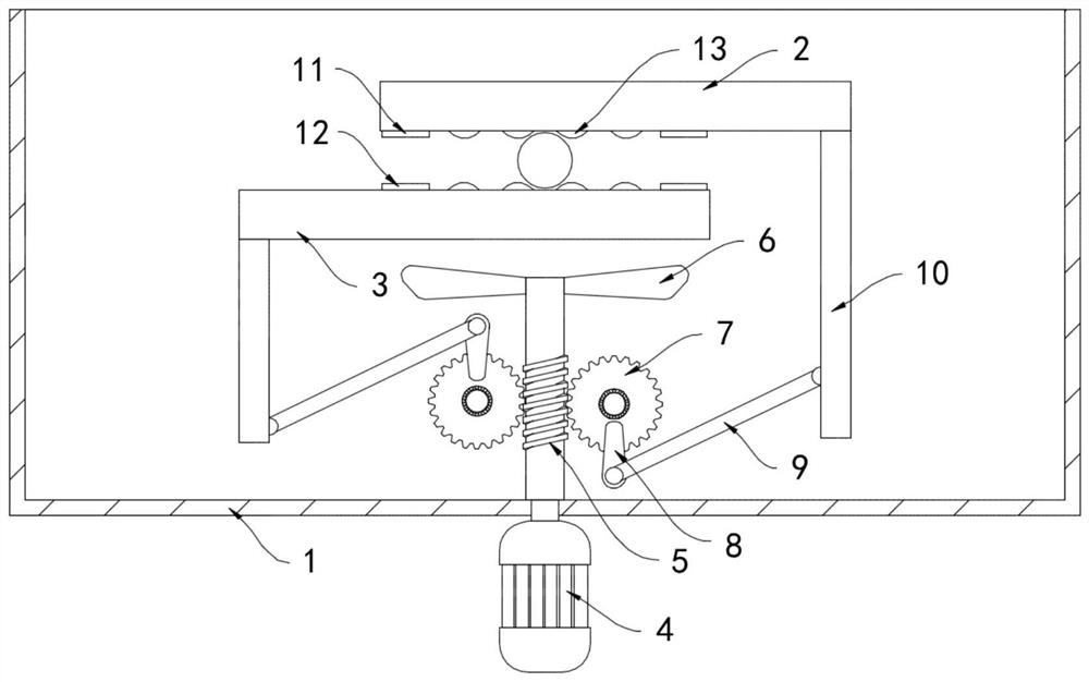
[0018] Such as figure 1 As shown, a tumbling type textile yarn dyeing device includes a dye liquor tank 1, an upper platen 2 and a lower platen 3 arranged horizontally are slidably connected to the inner wall of the dye liquor tank 1, and the lower surface of the upper platen 2 is fixed A permanent magnet piece 11 is connected, and the upper surface of the lower pressing plate 3 is fixedly connected with a magnet piece 12 that attracts the opposite poles of the permanent magnet piece 11. The side walls of the upper pressing plate 2 and the lower pressing plate 3 are provided with a plurality of Ribs 13 extending in the direction of the thread axis, the surface of the ribs 13 is arranged in an arc-shaped protrusion, when the upper pressing plate 2 and the lower pressing plate 3 are rolling and kneading the textile yarn, multiple ribs 13 repeatedly squeeze the textile yarn, Further improve the effect of exhaust dyeing on yarn.

[0019] A motor 4 is installed at the bottom of th...

Embodiment 2

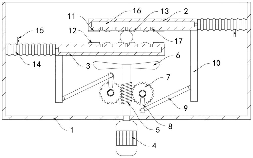
[0024] Such as figure 2 As shown, the difference between this embodiment and Embodiment 1 is that the upper platen 2 and the lower platen 3 are fixedly connected to the inner side wall of the dyeing liquid tank 1 through the flexible liquid bag 14, and the side wall of the flexible liquid bag 14 is fixedly connected. There is a one-way liquid inlet pipe 15, and the one-way liquid inlet pipe 15 only allows the dye solution in the dye solution tank 1 to enter the telescopic liquid bag 14, and the upper platen 2 and the lower platen 3 are provided with drains communicating with the telescopic liquid bag 14. The side walls of the liquid chamber 16 and the two liquid discharge chambers 16 adjacent to each other are equally spaced with a plurality of liquid discharge holes 17 .

[0025] In this embodiment, the upper platen 2 and the lower platen 3 repeatedly stretch and squeeze the telescopic liquid bag 14, and the telescopic liquid bag 14 sucks the dye solution in the dye liquid t...


PUM


Abstract

The invention belongs to the field of textile mechanical equipment, and particularly relates to a dyeing device for rolling and rubbing type textile yarn. The dyeing device comprises a dye liquor tank. A horizontally-arranged upper pressing plate and a horizontally-arranged lower pressing plate are slidingly connected to the inner side wall of the dye liquor tank, a motor is mounted at the bottomof the dye liquor tank, a worm is fixedly connected to an output shaft of the motor coaxially, the upper end of the worm stretches into the dye liquor tank and is coaxially provided with an impeller,two worm wheels are fixedly connected to the inner side wall of the dye liquor tank, the two worm wheels are located on the two sides of the worm and engaged with the worm, transmission rods are fixedly connected to the side walls of the two worm wheels, and the other ends of the two transmission rods are rotationally connected with connecting rods. The textile yarn can be rubbed, gas in yarn fibers is extruded out, seepage of dye liquor is accelerated, the dyeing efficiency is improved, meanwhile, when the yarn formed by combining multiple strands of single yarn is rolled and rubbed back andforth, the multiple strands of single yarn can be separated and then twisted, the dye liquor can conveniently evenly and fully seep for dyeing, and the product quality is improved.

Description

technical field [0001] The invention belongs to the field of textile machinery and equipment, and in particular relates to a dyeing device for tumbling textile yarns. Background technique [0002] Yarn is a textile made of two or more single yarns combined and twisted. It is used for weaving, rope making, thread making, knitting and embroidery, etc. It is divided into short fiber yarn, continuous filament, etc. . [0003] In the production process of yarn, dyeing is an extremely important step. The traditional dyeing method is to place the yarn in the dyeing solution tank and soak it. Due to the high viscosity of the dyeing solution, it needs to be soaked for a long time to ensure the dyeing effect. The dyeing liquid completely enters the inside of the yarn, which greatly reduces the working efficiency. At the same time, the yarn fiber is relatively fluffy. After being immersed in the dyeing liquid, the internal air forms bubbles and is difficult to discharge, which reduces...

Claims


Application Information

Patent Timeline
IPC IPC(8): D06B3/06D06B23/20D06B23/00
CPCD06B3/06D06B23/00D06B23/20D06B23/205
Inventor 丁青灶
Owner 盐城市海悦纺织有限公司
Why Eureka
Try Eureka