Steel beam hoisting method

A hoisting method and technology for steel girders, applied in bridges, bridge construction, transportation and packaging, etc., can solve problems such as difficult installation and large volume of steel girders, and achieve the effects of reducing construction period, improving construction quality, and simple and fast construction methods

Inactive Publication Date: 2020-10-30
CHINA RAILWAY BEIJING ENG BUREAU GRP TIANJIN ENG CO LTD +1
View PDF14 Cites 1 Cited by
  • Summary
  • Abstract
  • Description
  • Claims
  • Application Information

AI Technical Summary

Problems solved by technology

[0004] Therefore, the present invention provides a steel beam hoisting method to solve the problems of large steel beams and difficult installation in the prior art

Method used


Image

  • Steel beam hoisting method
  • Steel beam hoisting method

Examples


Embodiment 1

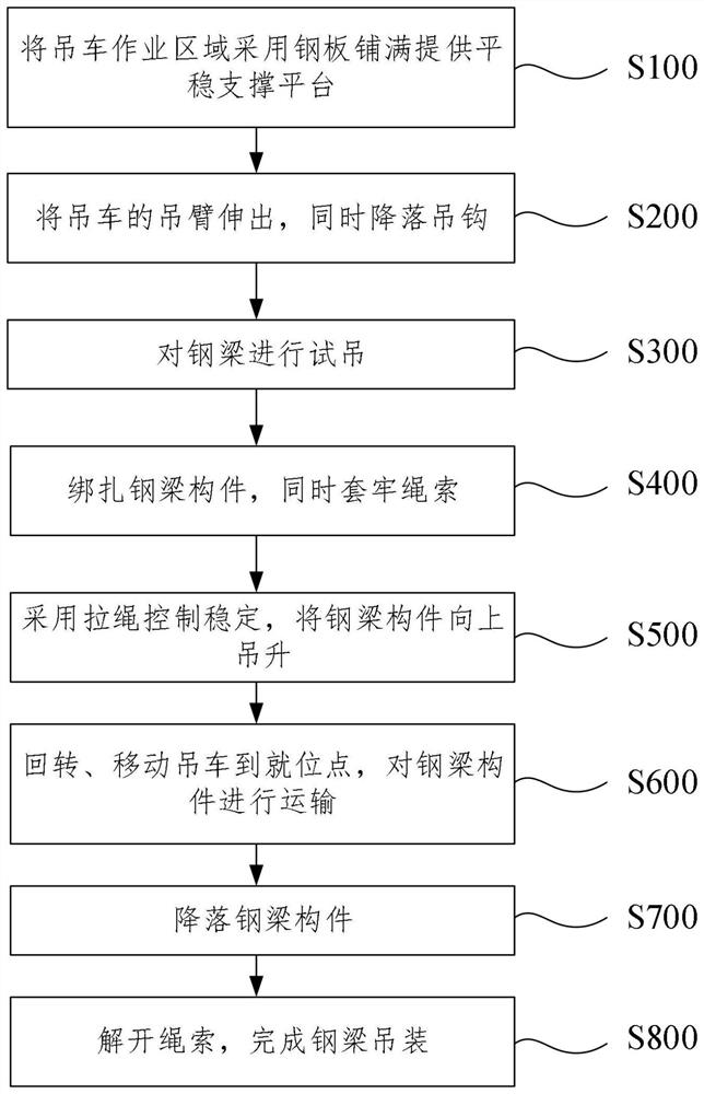
[0031] like figure 1 As shown, a steel beam hoisting method in this embodiment includes the following steps:

[0032] Step S100, covering the crane operation area with steel plates to provide a stable support platform;

[0033] Step S200, extending the boom of the crane and lowering the hook at the same time;

[0034] Step S300, carrying out trial lifting of the steel beam;

[0035] Step S400, tying up the steel beam members, while fastening the ropes;

[0036] Step S500, using a stay rope to control the stability, and hoisting the steel beam member upward;

[0037] Step S600, rotating and moving the crane to the in-position point, and transporting the steel beam member;

[0038] Step S700, dropping the steel beam member;

[0039] Step S800, untie the rope to complete the hoisting of the steel beam.

[0040] The technical effect achieved by this embodiment is: through a steel beam hoisting method of this embodiment, the construction method is simple and fast, and the hoi...

Embodiment 2

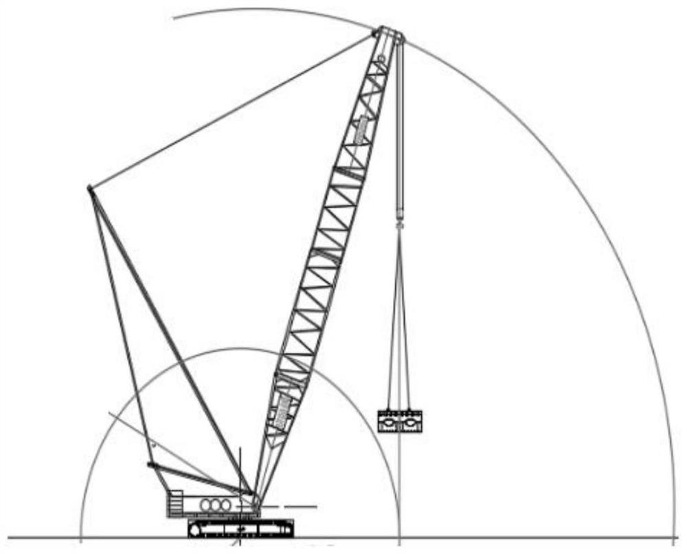
[0042] like figure 1 and figure 2 As shown, a steel girder hoisting method in this embodiment includes all the technical features in Embodiment 1. In addition, the thickness of the steel plate used in step S100 is 20cm to protect the road surface from being damaged and prevent the crane from hoisting the weight. Excessive concentration will damage the road surface.

[0043] Specifically, the steel girders transported to the site will be reassembled, assembled into a hoisting section, and the elevation of the pad stone of the main line bridge will be remeasured, and the steel girder support will be installed after the comparison with the design value is correct. After the support is installed, re-measure the elevation of the support; set up temporary supports; hoist the steel girders at different positions in sequence, and after the steel box girder welding and high bolt screwing are completed, unload and remove the temporary supports.

[0044] In some optional embodiments, ...

Embodiment 3

[0049] like figure 1 and figure 2 As shown, a steel beam hoisting method in this embodiment includes all the technical features in Embodiment 2. In addition, step S300 specifically includes: when the test hoisting reaches a height of 5cm to 10cm, perform a hover inspection , Check whether there are potential safety hazards, and continue to lift after confirming that it is correct. The steel beam is equipped with a lifting point, and the lifting point is connected to the wire rope with a snap ring when hoisting.

[0050] In some optional embodiments, step S400 specifically further includes: the steel girder binding should be firm, the binding point and the center of gravity of the steel beam component should be symmetrical to each other, and the center of the binding point should be aligned with the center of gravity of the object and higher than the center of gravity of the component, so that after the component is hoisted It is stable and does not cause accidents due to ove...


PUM


Abstract

The invention discloses a steel beam hoisting method. The steel beam hoisting method comprises the following steps that S100, a crane operation area is paved with steel plates to provide a stable supporting platform; S200, a suspension arm of the crane extends out, and a lifting hook descends; S300, trial hoisting is conducted on the steel beam; S400, steel beam components are bound, and ropes arefirmly sleeved; S500, a pull rope is adopted for controlling stability, and the steel beam components are lifted upwards; S600, the crane is rotated and moved to an in-place point, and the steel beamcomponents are transported; S700, the steel beam components are descended; and S800, the rope is unfastened, and steel beam hoisting is completed. The invention belongs to the technical field of building construction, and aims at solving problems that in the prior art, a steel beam is large in size and difficult to install. The steel beam hoisting method has the advantages that the construction method is simple and rapid, hoisting of the steel beam is effectively achieved, safety in the construction process is remarkably improved, the construction period is shortened, and the construction quality is improved.

Description

technical field [0001] The invention relates to the technical field of building construction, in particular to a steel beam hoisting method. Background technique [0002] In the existing bridge construction, the method of cantilever assembly is usually used for construction. With this method, it is necessary to press weight or anchor at the rear end of the steel beam, and the temporary engineering volume is huge. If this method is used for construction of long-span steel beams, the front end of the cantilever will be deformed greatly, and the construction of the pier at the front end of the cantilever will be difficult and dangerous. [0003] In addition, engineering steel girders have complex structures, tight construction schedules, many construction work areas, and difficult transportation. Engineering steel girders are all ultra-long and ultra-wide, and overall transportation is difficult to achieve; the complexity of the construction environment is also affected by cons...

Claims


Application Information

Patent Timeline
Patent Type & Authority Applications(China)
IPC IPC(8): E01D21/00B66C23/36B66C23/61
CPCB66C23/36B66C23/60E01D21/00
Inventor 杜宪武杨玉平周建军李邓任晓光王晶焦朋乐王磊冈陈学彬莒海彤
Owner CHINA RAILWAY BEIJING ENG BUREAU GRP TIANJIN ENG CO LTD
Why Eureka
Try Eureka