
Cast-in-place box girder construction method

A box girder construction and cast-in-situ technology, applied in bridges, bridge parts, bridge materials, etc., can solve the problems of difficult construction and poor safety of cast-in-place box girder.

Active Publication Date: 2020-10-30
ANHUI HIGHWAY BRIDGE ENG CO LTD
View PDF6 Cites 5 Cited by
  • Summary
  • Abstract
  • Description
  • Claims
  • Application Information

AI Technical Summary

Problems solved by technology

[0005] The purpose of the present invention is to provide a construction method of cast-in-place box girder to solve the problems of difficult construction and poor safety of cast-in-place box girder in the prior art

Method used


Image

  • Cast-in-place box girder construction method
  • Cast-in-place box girder construction method
  • Cast-in-place box girder construction method

Examples


Embodiment Construction

[0052] The present invention will be further described below in conjunction with the accompanying drawings and embodiments.

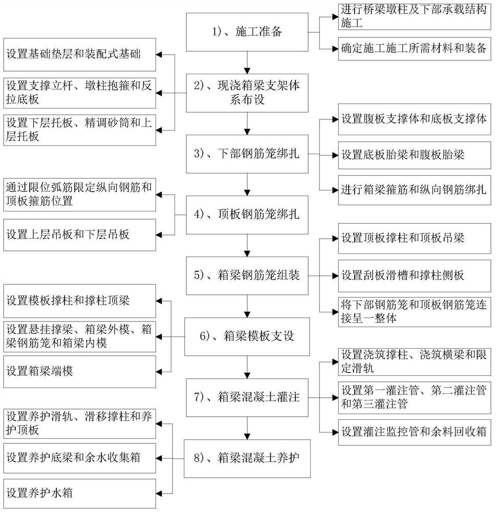
[0053] Such as Figure 1-Figure 13 Shown, the cast-in-place box girder construction method is characterized in that: comprises the following steps:

[0054] 1. Construction preparation:

[0055] Carry out the construction of bridge pier column 1 and its lower load-bearing structure, determine the concrete mix ratio, and prepare the devices required for construction;

[0056] 2. Layout of cast-in-place box girder support system:

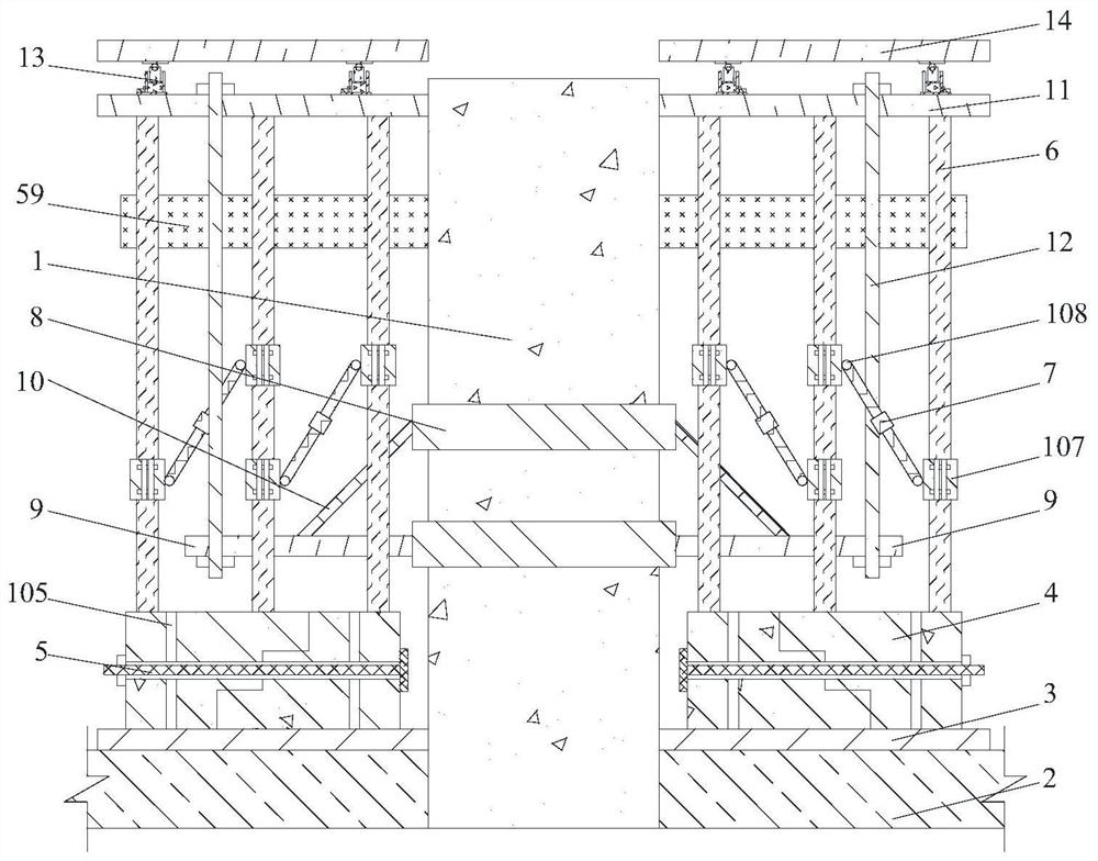
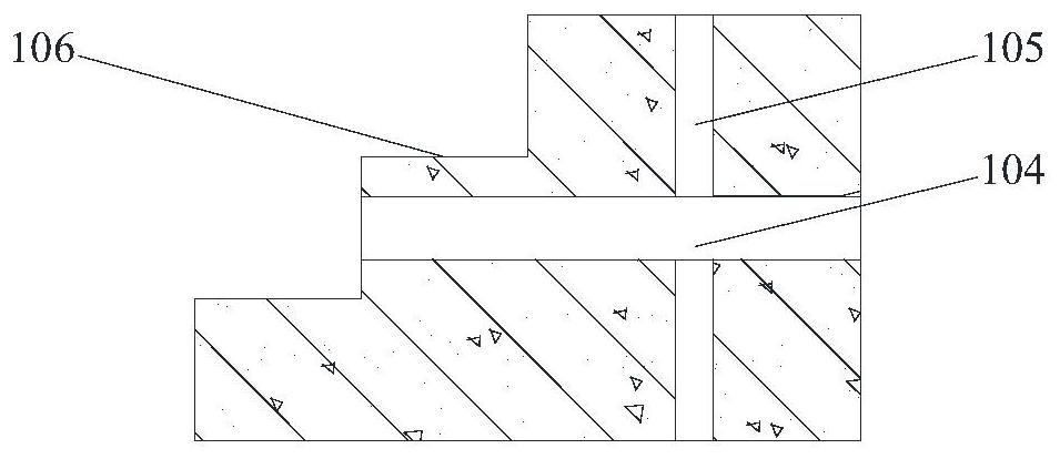
[0057] On the foundation soil 2 on both sides of the bridge pier column 1, a foundation cushion 3 and a prefabricated foundation 4 are arranged in sequence from bottom to top, wherein each prefabricated foundation 4 is composed of two parts that are superimposed and connected by step slopes, and The two parts of the prefabricated foundation 4 that are superimposed and connected up and down are firmly connected through the fo...


PUM


Abstract

The invention discloses a cast-in-place box girder construction method which comprises the steps that an assembly type foundation is connected with a foundation fastening bolt through a foundation connecting step, and a pier stud hoop is arranged on the outer side wall of a bridge pier stud; position control sand in the fine adjustment sand cylinder is recycled through the leaked sand recycling tank; a bottom plate inner support and a web plate inner support are arranged at the upper parts of the web plate moulding bed and the bottom plate moulding bed; a lower-layer lifting plate, an upper-layer lifting plate and a lifting connecting rod are arranged on the top plate reinforcement cage, and sliding clamping plates are arranged on the two sides of the top plate reinforcement cage; the space position of the outer mold side plate can be controlled by means of the side plate position control tenon and the side plate position control bolt, and the position of the box girder inner mold is controlled through the inner mold supporting body; the sliding material box can move along the limiting sliding rail and is provided with a pouring monitoring pipe. Support frame connecting hinges arearranged between the adjustable support frame and the bottom support frame and between the adjustable support frame and the top support frame, and the inclination angle of the adjustable support framecan be controlled through the angle adjusting vertical bolts and the angle adjusting transverse bolts. The accuracy of reinforcement cage positioning and concrete pouring construction control is improved, and the maintenance difficulty is reduced.

Description

technical field [0001] The invention relates to the field of bridge engineering, in particular to a construction method for a cast-in-place box girder that can improve the accuracy of steel cage positioning and concrete pouring construction control, reduce maintenance difficulty, and reduce the impact of construction on the environment. Background technique [0002] Cast-in-situ box girder bridges have the advantages of good overall performance, high structural rigidity, small deformation, and good seismic performance, and have been more and more widely used in modern highway and railway construction. During the construction of cast-in-place box girders, the preparation of steel cages, formwork support and concrete pouring have always been the key points and difficulties of project quality control. [0003] In the prior art, there is a construction method for cast-in-place box girders based on composite hoop brackets, which is characterized in that a built-in ring plate is p...

Claims


Application Information

Patent Timeline
Patent Type & Authority Applications(China)
IPC IPC(8): E01D21/00E01D2/04E01D19/02E02D27/00E02D19/20E01D101/26
CPCE01D21/00E01D2/04E01D19/02E02D27/00E02D19/12E01D2101/26Y02A30/60
Inventor 石怀远郑维王鑫陈勇杨庆肖鹏
Owner ANHUI HIGHWAY BRIDGE ENG CO LTD
Learn More