Multi-level air-flowing type industrial photocatalyst floor

An air flow, photocatalyst technology, applied in optics, optical components, separation methods, etc., can solve problems such as difficult air flow

Active Publication Date: 2020-10-30
文家洪
View PDF5 Cites 2 Cited by
  • Summary
  • Abstract
  • Description
  • Claims
  • Application Information

AI Technical Summary

Problems solved by technology

[0004] Photocatalysts, like other passive air purification products, require harmful substances in the air to come into contact with their surfaces to react, so the indoor air needs to ma

Method used


Image

  • Multi-level air-flowing type industrial photocatalyst floor
  • Multi-level air-flowing type industrial photocatalyst floor
  • Multi-level air-flowing type industrial photocatalyst floor

Examples


Embodiment

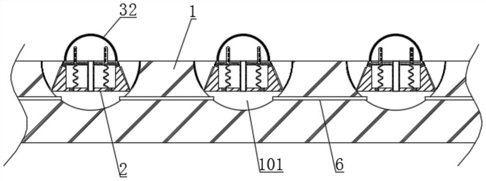
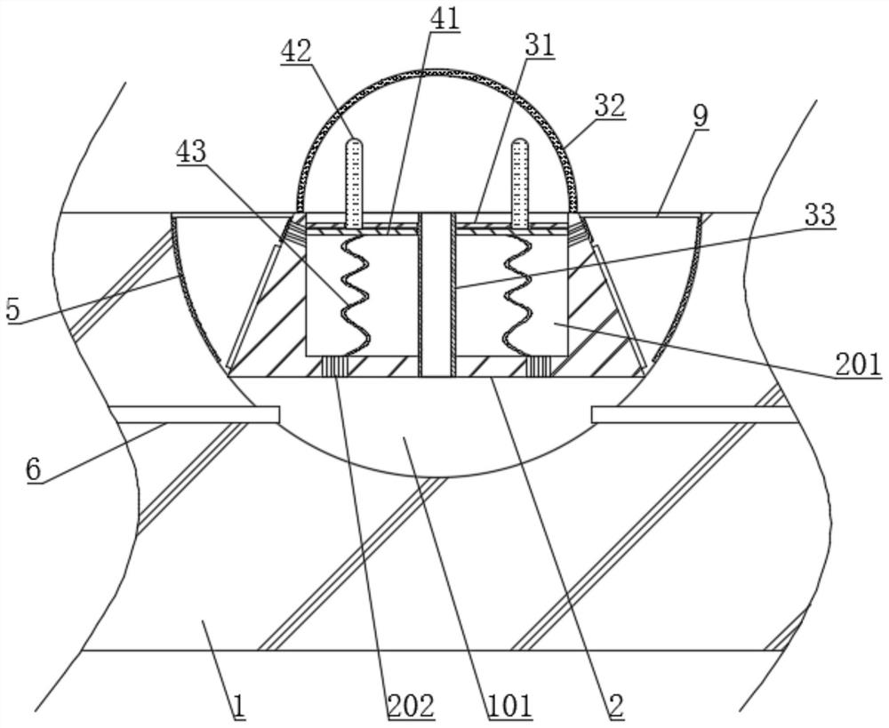
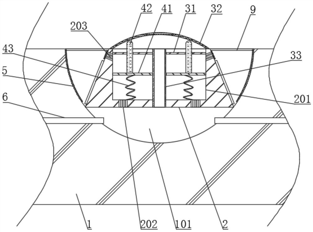
[0041] see figure 1 , a multi-stage airflow type industrial photocatalyst floor, including a floor 1, the upper end of the floor 1 is provided with a plurality of evenly distributed inner grooves 101, and the inside of the inner groove 101 is provided with a multi-stage air flow table, please refer to figure 2 , the inwall of inner groove 101 is coated with photocatalyst layer 5, and photocatalyst layer 5 can select titanium dioxide material for use, and photocatalyst layer 5 is positioned at the outside of multistage air flow table, and multistage air flow table includes the built-in platform 2 that is fixedly connected with inner groove 101 inwall, built-in platform The upper end of 2 is provided with a groove 201, and the interior of the groove 201 is provided with an inner jet mechanism. The inner jet mechanism includes a fixed plate 31 and an air guide tube 33 located inside the groove 201. The air guide tube 33 runs through the fixed plate 31 and connects with the fixed ...


PUM


Abstract

The invention discloses a multi-level air-flowing type industrial photocatalyst floor and belongs to the field of photocatalyst floors. A plurality of multi-level air-flowing tables are arranged in the floor, and thus inner jet flow mechanisms and outer jet flow mechanisms in the floor are triggered due to treading in the walking process of people, so that on one aspect, outside air constantly flows in and out of the interiors of the multi-level air-flowing tables due to the pressure intensity changes brought by the outer jet flow mechanisms, the mobility of the outside air is enlarged, and sufficient purification of the outside air by photocatalyst layers is achieved; and on the other aspect, an air flowing process is achieved between the multi-level air-flowing tables and the parts adjacent to the peripheries of the multi-level air-flowing tables due to the air flow changes brought by the inner jet flow mechanisms, and thus flowing of outside air adjacent to the multi-level air-flowing tables is intensified accordingly, so that multiple effects are promoted through one component, the mobility of the surrounding air near the photocatalyst layers is further improved, the purifyingeffect is effectively improved, and the photocatalyst layers are not likely to be stripped by abrasion borne in the walking process of people.

Description

technical field [0001] The invention relates to the field of photocatalyst floors, more specifically, to a multi-stage airflow type industrial photocatalyst floor. Background technique [0002] Photocatalyst, also called photocatalyst, is a general term for semiconductor materials with photocatalytic function represented by nano-scale titanium dioxide. The representative photocatalyst material is titanium dioxide, which can produce strong oxidizing substances (such as hydroxyl radicals, oxygen, etc.) under light irradiation, and can be used to decompose organic compounds, some inorganic compounds, bacteria and viruses. In daily life, photocatalysts can effectively degrade toxic and harmful gases in the air such as formaldehyde, efficiently purify the air, and at the same time, can effectively kill a variety of bacteria, and can decompose and harmlessly treat the toxins released by bacteria or fungi. As long as it is not worn or peeled off, the photocatalyst itself will not ...

Claims


Application Information

Patent Timeline
IPC IPC(8): E04F15/02E04F15/18B01D53/86G02B7/182
CPCE04F15/02E04F15/181B01D53/007B01D53/86G02B7/182B01D2255/802
Inventor 文家洪
Owner 文家洪
Why Eureka
Try Eureka