Regional cooperative reinforced fluidized bed heater

A fluidized bed and heat extractor technology, applied in fluidized bed heat exchangers, catalytic cracking, heat exchanger shells, etc., can solve the limitation of improving heat exchange efficiency and reduce the internal stability of fluidized bed heat extractors And other issues

Pending Publication Date: 2020-10-30
CHINA UNIV OF PETROLEUM (BEIJING)
View PDF7 Cites 6 Cited by
  • Summary
  • Abstract
  • Description
  • Claims
  • Application Information

AI Technical Summary

Problems solved by technology

[0005] The purpose of the present invention is to provide a fluidized bed heat extractor with regional synergistic strengthening, which is used to solve the problem of limited improvement of heat exchange efficiency caused by the strengthening of local areas and the impact and wear of catalyst solid particles on heat exchange tubes to reduce fluidization. The problem of the internal stability of the bed heat extractor, in order to realize the stable and efficient operation of the fluidized bed heat extractor

Method used


Image

  • Regional cooperative reinforced fluidized bed heater
  • Regional cooperative reinforced fluidized bed heater
  • Regional cooperative reinforced fluidized bed heater

Examples


Embodiment 1

[0042] Embodiment 1 provides a fluidized bed heat extractor with regional synergistic enhancement, and its structure is described in detail below.

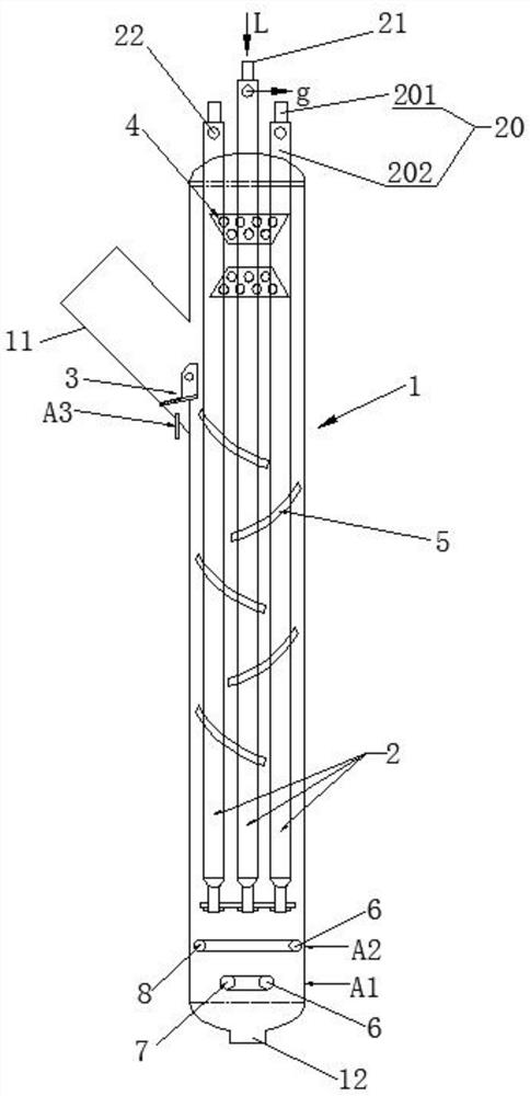
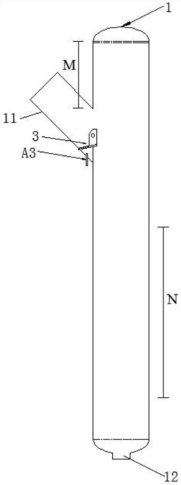
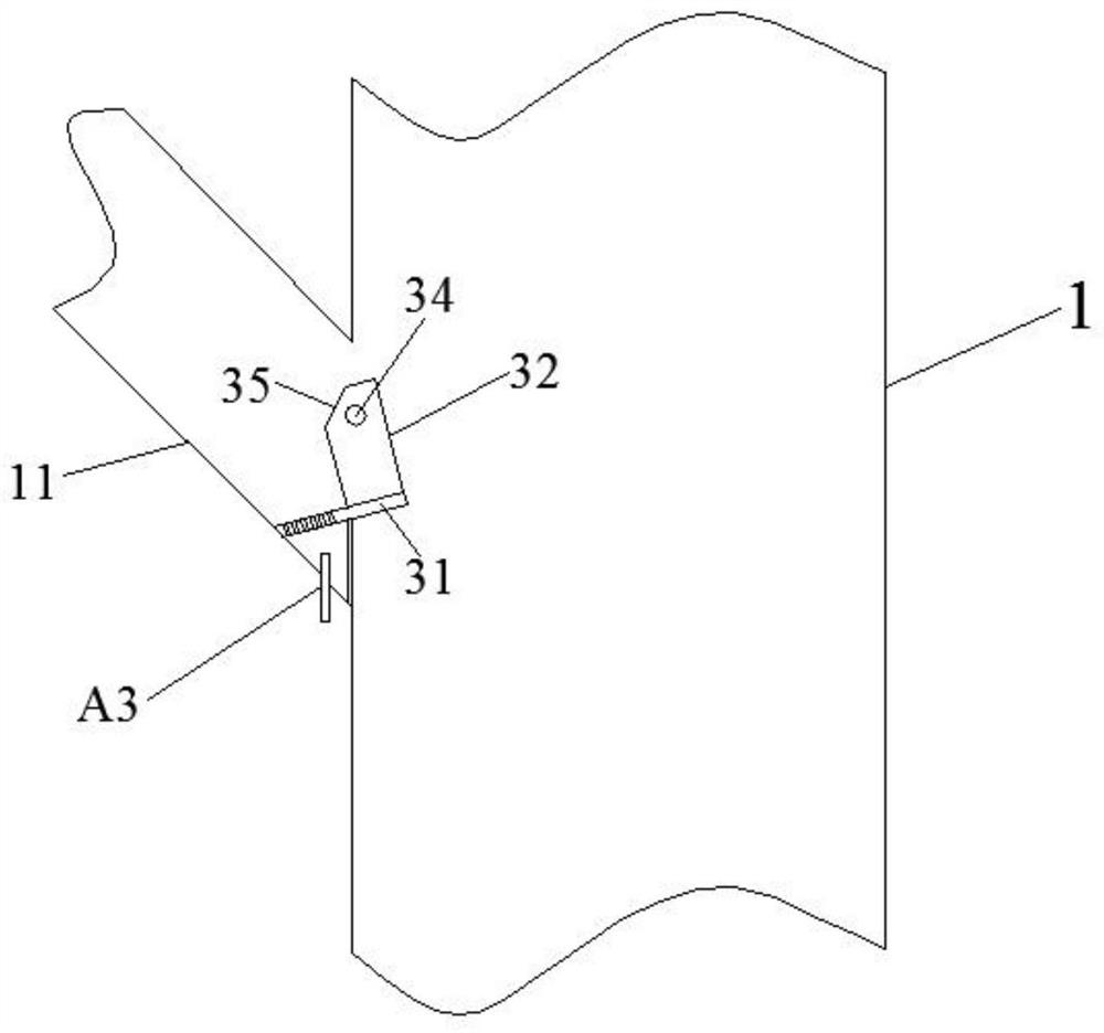
[0043] reference figure 1 with figure 2 , The fluidized bed heat extractor includes a shell 1, which is a round tank type and is set upright. A plurality of heat exchange tubes 20 are vertically distributed in the shell 1, and the upper part of the shell 1 is provided with a catalyst inlet. The bottom of the casing 1 is provided with a catalyst outlet 12, and the inside of the casing 1 is divided into a catalyst inlet influence zone, a dilute phase zone M at the upper part, a dense phase zone N at the lower part, and a gas distributor influence zone at the bottom; Area M and dense phase area N are respectively located above and below the catalyst inlet influence zone. The catalyst inlet is inclined upwardly with a catalyst inlet inclined pipe 11, and the catalyst inlet in the catalyst inlet inclined pipe 11 is provided with a region...

Embodiment 2

[0074] On the basis of Embodiment 1, Embodiment 2 provides another structure and placement method of the dilute phase guide vane 4 and the dense phase guide vane 5, and the structure and placement method will be described in detail below.

[0075] reference Picture 9 , The dilute phase guide vane 4 and the dense phase guide vane 5 are both bent plate structures, and their longitudinal section is in the shape of a broken line, that is, the dilute phase guide vane 4 and the dense phase guide vane 5 are both broken line-shaped bent plates. The dilute phase guide vane 4 is provided with a plurality of dilute phase guide vane guide holes 40, and the plurality of dilute phase guide vanes 4 are arranged spirally from bottom to top around the longitudinal center line of the casing 1 in the dilute phase region M Or they are staggered from bottom to top along the longitudinal centerline of the housing 1. The dense phase guide vane 5 is provided with a plurality of dense phase guide vane g...


PUM


Abstract

The invention discloses a regional cooperative reinforced fluidized bed heater. The regional cooperative reinforced fluidized bed heater comprises a shell, wherein a catalyst inlet is formed in the upper part of the shell, the interior of the shell is divided into a catalyst inlet influence area, a dilute phase area, a dense phase area and a gas distributor influence area, a catalyst inlet inclined pipe is arranged at the catalyst inlet upwards in an inclined mode, a regional particle distributor is arranged at the catalyst inlet in the catalyst inlet inclined pipe, a plurality of dense phasedeflectors are arranged in the dense phase area, a plurality of dilute phase deflectors are arranged in the dilute phase area, and double gas distributors are arranged in the gas distributor influencearea. According to the regional cooperative reinforced fluidized bed heater, the problems of low internal stability of the fluidized bed heater due to wear and erosion of inlet catalysts to heat exchange bundles and low heat exchange efficiency caused by the limitation of improvement of heat exchange efficiency due to partial regional reinforcement are preferably solved at the same time, so thatthe stable and efficient operation of the fluidized bed heater is realized.

Description

Technical field [0001] The invention relates to a fluidized bed heat extractor, in particular to a fluidized bed heat extractor with regional synergistic enhancement. Background technique [0002] In recent years, crude oil in the world oil market has become heavier, and as a catalytic cracking technology for heavy oil lightening, more and more attention has been paid. Catalytic cracking raw materials continue to be heavier, and the increase in coke generation rate makes the reaction-regeneration system excess heat. The excess heat needs to be removed in time to maintain the heat balance of the reaction-regeneration system. Therefore, the excess heat carried by the catalyst is removed from the reaction- The removal of the regeneration system is crucial. The heavy oil catalytic cracking unit generally uses an external heat extractor installed outside the regenerator, which can remove the excess heat in the reaction-regeneration system without affecting the normal operation of the...

Claims


Application Information

Patent Timeline
Patent Type & Authority Applications(China)
IPC IPC(8): F28D13/00F28F9/22F28F9/24B01J8/24
CPCF28D13/00F28F9/22F28F9/24B01J8/24F28F2009/228B01J8/1827B01J8/1836B01J8/12B01J8/34B01J2208/00132B01J8/1881B01J2208/00752B01J2208/0084F28F2009/222C10G11/18B01J2208/00893B01J2208/00938
Inventor 卢春喜李建涛姚秀颖
Owner CHINA UNIV OF PETROLEUM (BEIJING)
Why Eureka
Try Eureka