
Solar photovoltaic panel mounting bracket

A technology of solar photovoltaic panels and mounting brackets, which is applied to the support structure of photovoltaic modules, photovoltaic modules, and photovoltaic power generation. small effect

Inactive Publication Date: 2020-10-30
JIANGSU HONGDE TECH DEV CO LTD
View PDF1 Cites 0 Cited by
  • Summary
  • Abstract
  • Description
  • Claims
  • Application Information

AI Technical Summary

Problems solved by technology

[0002] As a clean energy source, solar photovoltaic power generation system is a new type of power generation system that uses the photovoltaic effect of solar cell semiconductors to directly convert the heat energy radiated by sunlight into electrical energy. It is widely used in the field of lighting. The existing solar photovoltaic power generation system Generally, a large number of photovoltaic panels are used as the conversion of solar energy. The installation method of photovoltaic panels is generally to integrate several photovoltaic panels on a frame to form a large number of photovoltaic panel combinations. During the installation process of traditional photovoltaic panels, it needs Use bolts to screw the four corners of the photovoltaic panel to the frame. During installation, each photovoltaic panel needs to be installed separately. When adjusting the angle, generally you can only adjust the angle of the frame as a whole, which is not flexible enough, which leads to the functional failure of traditional photovoltaic panels. single problem arises

Method used


Image

  • Solar photovoltaic panel mounting bracket
  • Solar photovoltaic panel mounting bracket
  • Solar photovoltaic panel mounting bracket

Examples


Embodiment Construction

[0026] In the following, the present invention will be further clarified in conjunction with specific embodiments. It should be understood that these embodiments are only used to illustrate the present invention and not to limit the scope of the present invention. After reading the present invention, those skilled in the art will give various equivalents to the present invention. All the modifications fall within the scope defined by the appended claims of this application.

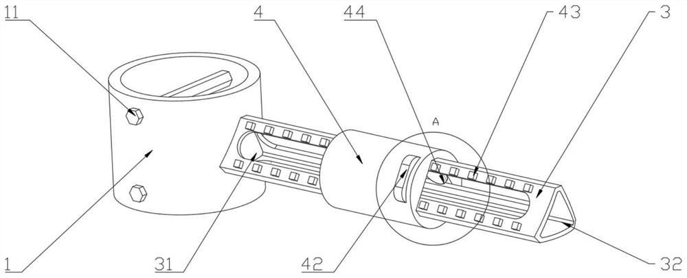
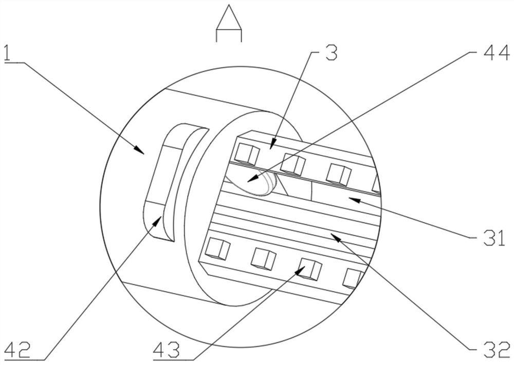
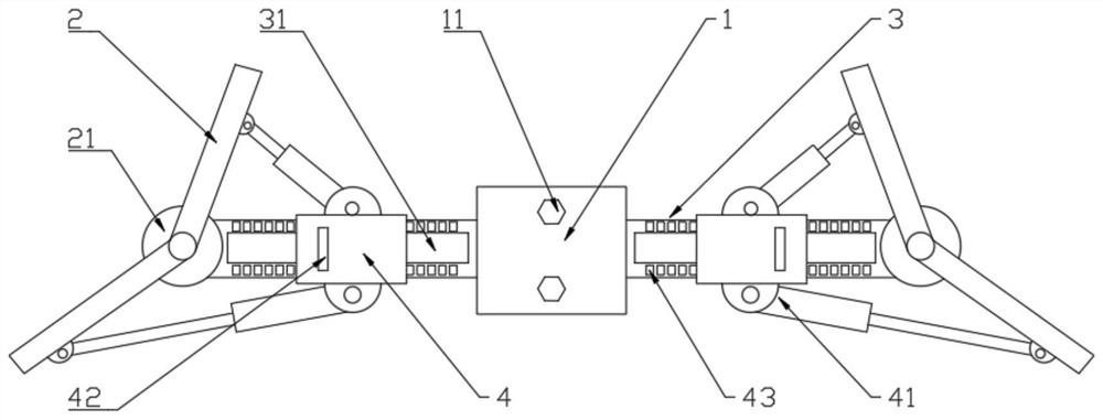
[0027] It should be noted that similar reference numerals and letters indicate similar items in the following drawings. Therefore, once an item is defined in one drawing, it does not need to be further defined and explained in the subsequent drawings.

[0028] In the description of the present invention, it should be noted that the orientation or positional relationship indicated by the terms "vertical", "outer peripheral surface", etc. is based on the orientation or positional relationship shown in the drawing...


PUM


Abstract

The invention discloses the field of lighting equipment, and particularly relates to a solar photovoltaic panel mounting bracket. The solar photovoltaic panel mounting bracket is arranged above a lamppost, and the bracket comprises a fixing sleeve which is arranged on the lamp post in a holding manner, mounting plates which are symmetrically arranged on the two sides of the fixing sleeve and connected to the fixing sleeve through connecting arms, an adjusting part which is used for adjusting the rotating amplitudes of the mounting plates relative to the rotating shaft, wherein rotating shaftsare arranged in the middles of the mounting plates, ends of the connecting arms are fixedly connected with the fixing sleeve, and the other ends are connected with the rotating shafts; the adjustingpart comprises fixed seats slidably mounted on the connecting arms, a plurality of telescopic pieces are arranged on the periphery of the fixed seats, one end of each telescopic piece is fixedly connected with a fixed seat, the other end of each telescopic piece is fixedly connected with a mounting plate, clamping blocks are arranged in the fixed seats, and clamping teeth matched with the clampingblocks are formed on the outer surfaces of the connecting arms. The bracket has a reasonable structure, and the rotation angle of a photovoltaic panel can be effectively adjusted.

Description

Technical field [0001] The invention relates to the technical field of lighting equipment, in particular to a solar photovoltaic panel mounting bracket. Background technique [0002] As a kind of clean energy, solar photovoltaic power generation system is a new type of power generation system that uses the photovoltaic effect of solar cell semiconductors to directly convert the heat energy of solar radiation into electrical energy. It is widely used in the field of lighting. The existing solar photovoltaic power generation system In general, a large number of photovoltaic panels are used as solar energy conversion. The installation method of photovoltaic panels is generally to integrate several photovoltaic panels on a frame to form a large number of photovoltaic panel combinations. In the installation process of traditional photovoltaic panels, Use bolts to screw the four corners of the photovoltaic panel to the frame. When installing, each photovoltaic panel needs to be install...

Claims


Application Information

Patent Timeline
Patent Type & Authority Applications(China)
IPC IPC(8): H02S20/30F21S9/03F21V23/00
CPCH02S20/30F21S9/035F21V23/02Y02E10/50
Inventor 张爱军夏春远
Owner JIANGSU HONGDE TECH DEV CO LTD
Learn More