
Welding jig for liquid crystal module FPC

A liquid crystal module and welding jig technology, applied in welding equipment, manufacturing tools, components of lighting devices, etc., can solve the problems of not being able to weld the FPC to be welded, affecting the welding operation, etc., and achieve the effect of reducing the amount of errors

Inactive Publication Date: 2020-11-03
珠海晨新科技有限公司
View PDF0 Cites 0 Cited by
  • Summary
  • Abstract
  • Description
  • Claims
  • Application Information

AI Technical Summary

Problems solved by technology

[0003] At present, there are many kinds of welding jigs for liquid crystal module FPC on the market, but these welding jigs are common. Since the angle of the welding jig is generally fixed, when manually welding the liquid crystal module FPC, the side of the FPC cannot be The place to be welded is welded, and when welding some subtle parts, insufficient light source will affect the welding operation

Method used


Image

  • Welding jig for liquid crystal module FPC
  • Welding jig for liquid crystal module FPC
  • Welding jig for liquid crystal module FPC

Examples


Embodiment 1

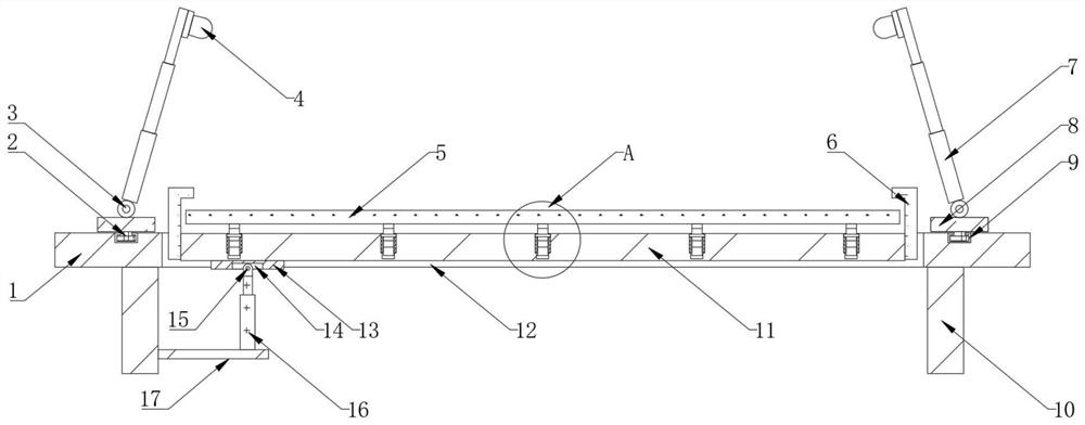
[0024] see Figure 1~2 , in the embodiment of the present invention, the welding fixture of the liquid crystal module FPC includes a workbench 1, the four corners of the bottom end of the workbench 1 are connected with supporting feet 10, and the top of the workbench 1 is provided with a mounting hole 12, and the workbench 1 The bottom is provided with a mounting frame 17, and the top of the workbench 1 is provided with an FPC placing plate 11, and both sides of the FPC placing plate 11 are connected with fixing fixtures 6, and the top of the mounting frame 17 is equipped with an electric telescopic rod 16, and the electric telescopic rod 16 The top is provided with a second slider 15, and one side of the bottom end of the FPC placement plate 11 is connected with a connecting plate 13, and the bottom end of the connecting plate 13 is provided with a second chute 14, and the front and rear parts of the mounting hole 12 are provided with a rotating shaft 19.

[0025] Wherein, bo...

Embodiment 2

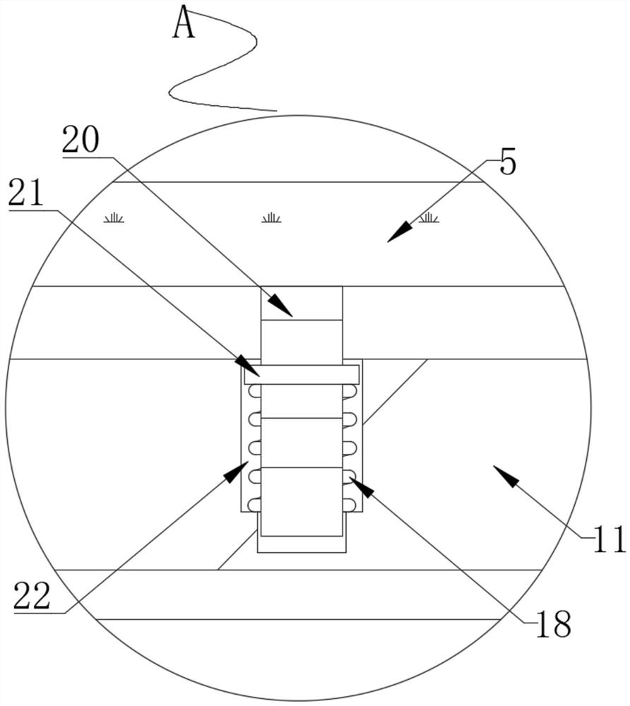
[0031] refer to figure 1 , 3 And 4, the welding jig of liquid crystal module FPC, this embodiment is compared with embodiment 1, also includes that the top of FPC placement board 11 is provided with balance board 5, and the top of FPC placement board 11 is equidistantly provided with several grooves 22. A limit spring 18 is installed inside the groove 22, and a plurality of adjusting rods 20 are equidistantly connected to the bottom end of the balance board 5, and the outside of the adjusting rod 20 is sleeved with a limit ring 21.

[0032] Wherein, one end of the limiting spring 18 is connected to the inner side of the groove 22 , and the other end of the limiting spring 18 is connected to the bottom end of the limiting ring 21 .

[0033] Working principle: Since the surface of the liquid crystal module is not completely flat, when the liquid crystal module is placed on the FPC placement board 11, the unevenness of the liquid crystal module will make the liquid crystal modul...


PUM


Abstract

The invention discloses a welding jig for a liquid crystal module FPC. The jig comprises a workbench, supporting legs are connected to the four corners of the bottom end of the workbench correspondingly, a mounting hole is formed in the top end of the workbench, a mounting frame is arranged at the bottom of the workbench, an FPC containing plate is arranged at the top end of the workbench, and fixing clamps are connected to the two sides of the FPC containing plate correspondingly. An electric telescopic rod is installed at the top end of the mounting frame, a second sliding block is arrangedat the top end of the electric telescopic rod, a connecting plate is connected to one side of the bottom end of the FPC containing plate, and a second sliding groove is formed in the bottom end of theconnecting plate. Through the electric telescopic rod, the second sliding block, the second sliding groove, the connecting plate, a hinge, the mounting frame, the mounting hole and a rotating shaft,the FPC containing plate can conveniently rotate by a certain angle in the mounting hole, and the side surface, to be welded, of a liquid crystal module faces a user, so that the liquid crystal moduleis convenient to weld by the user.

Description

technical field [0001] The invention relates to the technical field of liquid crystal module production equipment, in particular to a welding fixture for liquid crystal module FPC. Background technique [0002] The liquid crystal module refers to the combination of LCD screen + LED backlight + PCB board + iron frame. The principle of liquid crystal display is that the backlight assembly emits uniform surface light, and the light is transmitted to our eyes through the liquid crystal screen. The function of the screen is to process these lights by pixels to display images. In the production process of the liquid crystal module, various electronic components need to be welded on the FPC of the liquid crystal module. The welding fixture is a welding fixture designed and manufactured according to the size coordinate points of the shape of the welded part calibrated when the welding product is designed. [0003] At present, there are many kinds of welding jigs for liquid crysta...

Claims


Application Information

Patent Timeline
IPC IPC(8): B23K3/08H05K3/34F21V33/00
CPCB23K3/08B23K3/087F21V33/00H05K3/34
Inventor 何鵾周雄津杨通
Owner 珠海晨新科技有限公司
Learn More