Movable stirrer

A mixer and mixing box technology, used in cement mixing devices, control devices, cleaning hollow objects, etc., can solve the problems of reducing the life of the mixer, the complexity of the mixer operation, concrete hardening, manual opening, etc., to reduce the operation burden and increase transmission. Power, the effect of reducing the burden on the car

Inactive Publication Date: 2020-11-03
杭州汇安建筑节能科技有限公司
View PDF0 Cites 0 Cited by
  • Summary
  • Abstract
  • Description
  • Claims
  • Application Information

AI Technical Summary

Problems solved by technology

However, it is very inconvenient to manually open the valve to get the mixed concrete out of the mixer. Moreover, due to the fluidity and viscosity of the concrete, there will often be a layer of

Method used


Image

  • Movable stirrer
  • Movable stirrer
  • Movable stirrer

Examples


Embodiment Construction

[0025] In order to enable those in the technical field to better understand the solutions of the present invention, the technical solutions in the embodiments of the present invention will be clearly and completely described below in conjunction with the drawings in the embodiments of the present invention.

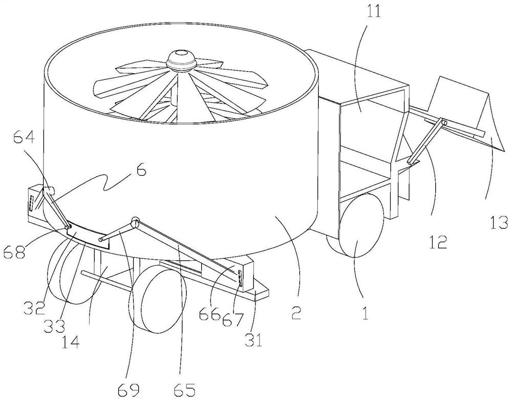
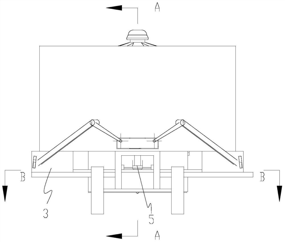
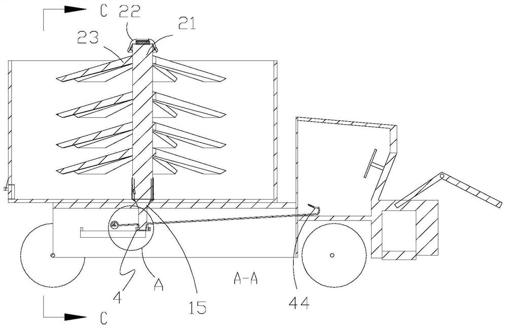
[0026] Such as Figure 1-12Shown, a kind of movable mixer comprises vehicle frame 1, first support plate 14, mixing box 2, transmission device 3, cockpit 11, hydraulic rod 12, bucket 13, motor 15; First support plate 14 is set On the frame 1, it is a C-shaped notch downward, and both ends are fixedly connected to the frame 1; the mixing box 2 is set on the first support plate 14, and the whole is circular and thin-walled; the transmission device 3 is set on the frame On the frame 1, located at the bottom of the vehicle, driven by the force of the rotating shaft; the cockpit 11 is set on the frame 1, with a protective glass on the top, and the hydraulic rod 12 is set on th...


PUM


Abstract

The invention discloses a movable stirrer which comprises a frame 1, a first supporting plate 14 arranged on the frame 1, a stirring box 2 arranged on the first supporting plate 14, a mud scraping device 7 arranged on the stirring box 2, a transmission device 3 arranged on the frame 1, a driving cabin 11 arranged on the frame 1 and a motor 15 arranged on the first supporting plate 14; and the transmission device 3 comprises a transmission assembly 5 arranged on the frame 1, a plurality of second supporting plates 31 arranged on the frame 1, a plurality of second transmission assemblies arranged on the second supporting plates 31 and a plurality of third transmission assemblies arranged on the second transmission assemblies. According to the movable stirrer, by additionally arranging a gearand the transmission device 3, a discharging plate 33 behind the stirring box 2 can be adjusted and controlled in the driving cabin 11, so that concrete in the stirring box 2 is discharged from the stirring box 2, an additional motor 15 is not needed, and help of other people is not needed; and mud scraping blades 84 are additionally arranged, so that the problem that the concrete at the bottommost part of the stirring box 2 cannot be discharged from the stirring box 2 due to compaction is solved.

Description


Claims


Application Information

Patent Timeline
Owner 杭州汇安建筑节能科技有限公司
Why Eureka
Try Eureka