
Stainless steel bolt annealing device and annealing process

An annealing device, stainless steel technology, applied in the direction of manufacturing tools, furnaces, heat treatment equipment, etc., can solve the problems of uneven annealing, bolt annealing device without bolt annealing furnace, screw annealing effect is not good, etc., to achieve easy support and uniform annealing Effect

Inactive Publication Date: 2020-11-03
HAIYAN JINNIU FASTENERS CO LTD
View PDF7 Cites 0 Cited by
  • Summary
  • Abstract
  • Description
  • Claims
  • Application Information

AI Technical Summary

Problems solved by technology

[0004] The purpose of the present invention is to provide a stainless steel bolt annealing device and annealing process, to solve the problem that the existing bolt annealing device proposed in the above background technology does not have a special bolt annealing furnace, and the screw cannot be placed through the spacing between the supporting rollers, thereby It is inconvenient to perform rotary annealing on the screw, which is likely to cause uneven annealing, and it is not possible to set up partitions according to the length of the screw, which may cause the problem that the annealing effect of the screw piled up is not good

Method used


Image

  • Stainless steel bolt annealing device and annealing process
  • Stainless steel bolt annealing device and annealing process
  • Stainless steel bolt annealing device and annealing process

Examples


Embodiment Construction

[0036] The following will clearly and completely describe the technical solutions in the embodiments of the present invention with reference to the accompanying drawings in the embodiments of the present invention. Obviously, the described embodiments are only some, not all, embodiments of the present invention. Based on the embodiments of the present invention, all other embodiments obtained by persons of ordinary skill in the art without making creative efforts belong to the protection scope of the present invention.

[0037] In the description of the present invention, unless otherwise stated, the meaning of "plurality" is two or more; the terms "upper", "lower", "left", "right", "inner", "outer" , "front end", "rear end", "head", "tail", etc. indicate the orientation or positional relationship based on the orientation or positional relationship shown in the drawings, and are only for the convenience of describing the present invention and simplifying the description, rather...


PUM


Abstract

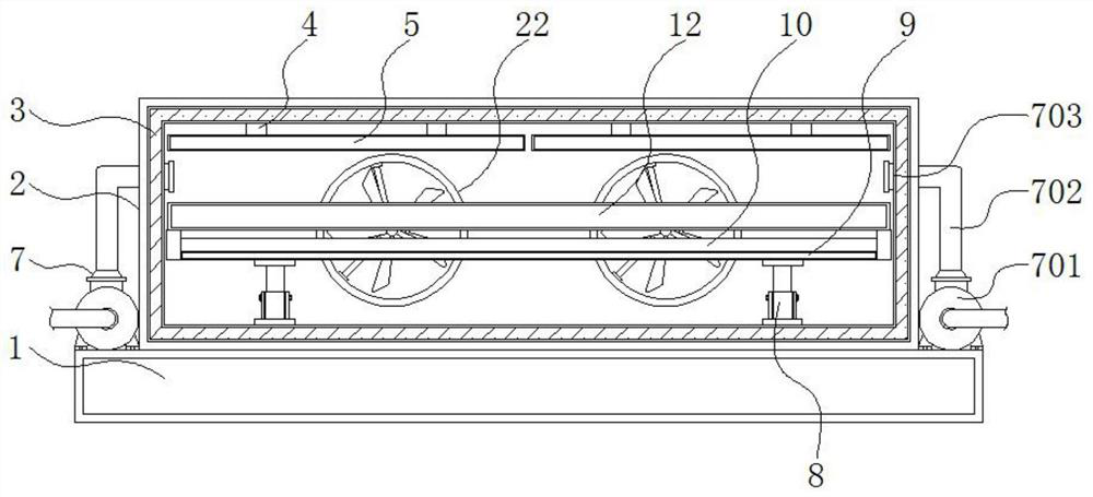
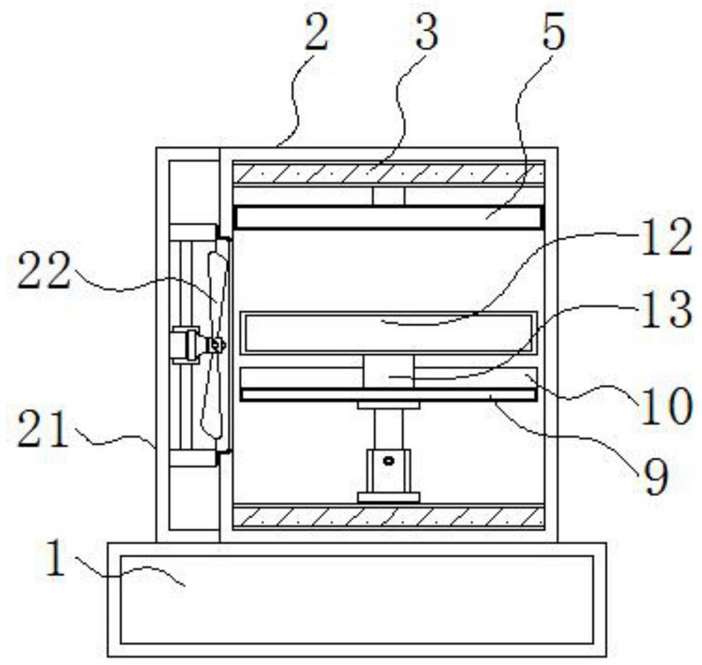
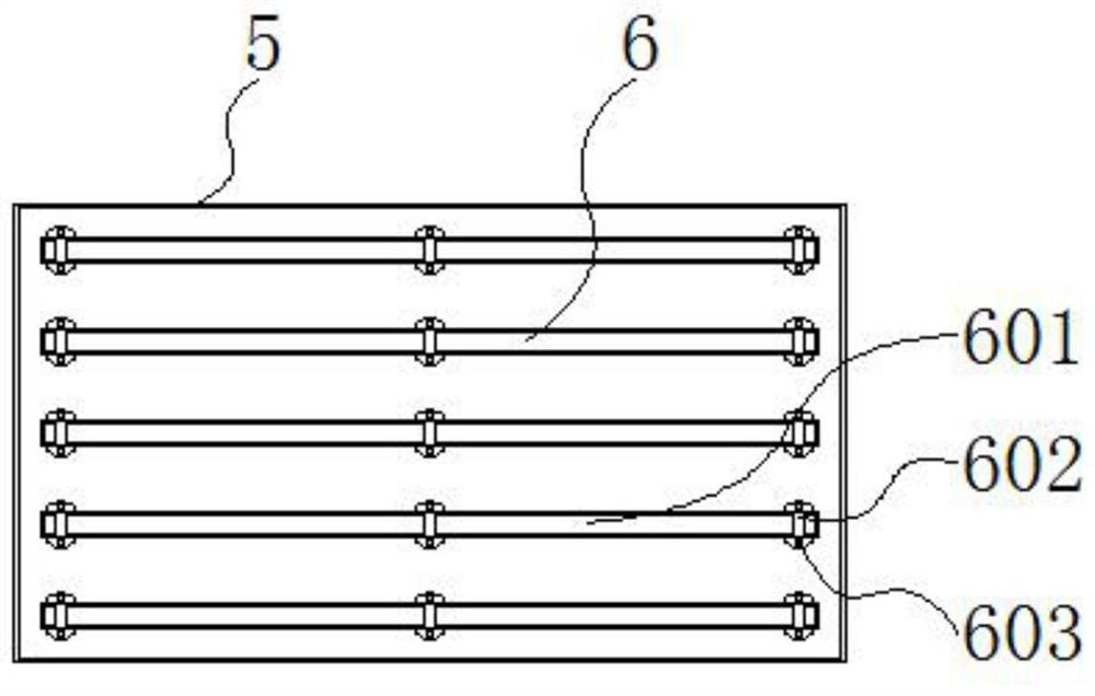
The invention discloses a stainless steel bolt annealing device and an annealing process, and relates to the technical field of bolt annealing. The stainless steel bolt annealing device comprises an annealing furnace, a heating mechanism and gas inlet mechanisms, a base is installed below the annealing furnace, a thermal insulation layer is arranged on the inner wall of the annealing furnace, a connecting rod is fixed to the upper portion of the interior of the annealing furnace, and an insulating plate is installed below the connecting rod; and the heating mechanism is arranged on the lower side of the insulating plate, the gas inlet mechanisms are installed on the two sides of the outer portion of the annealing furnace, a supporting rod is installed on the lower portion of the interior of the annealing furnace, a bearing plate is fixed to the upper portion of the supporting rod, a protective frame is fixed to the outer side of the bearing plate, and a ventilation groove is formed inthe bearing plate. The stainless steel bolt annealing device and the annealing process have the beneficial effects that the annealing furnace of the device and a rear cavity are of an integrated structure, air circulation of hot air in the annealing furnace can be accelerated conveniently through two sets of symmetrically-arranged annealing fans in the rear cavity, and therefore heat in the annealing furnace is distributed more evenly, and the annealing quality can be better improved.

Description

technical field [0001] The invention relates to the technical field of bolt annealing, in particular to a stainless steel bolt annealing device and an annealing process. Background technique [0002] A bolt belongs to a mechanical part and is a cylindrical threaded fastener with a nut. During the processing of stainless steel bolts, it needs to be annealed. Annealing is a metal heat treatment process, which refers to slowly heating the metal to a certain temperature, keeping it for a sufficient time, and then cooling it at an appropriate speed. The purpose is to reduce hardness, improve machinability; eliminate residual stress, stabilize size, reduce deformation and crack tendency; refine grain, adjust structure, and eliminate structure defects. [0003] The existing bolt annealing device does not have a special bolt annealing furnace, and the screw cannot be placed through the distance between the rollers, so that it is not convenient to rotate the annealing of the screw, ...

Claims


Application Information

Patent Timeline
IPC IPC(8): C21D9/00C21D1/26C21D1/34
CPCC21D1/26C21D1/34C21D9/0025C21D9/0062C21D9/0093
Inventor 王金玉
Owner HAIYAN JINNIU FASTENERS CO LTD
Learn More