Novel bladeless air conditioner fan

An air-conditioning fan, a new type of technology, applied in the field of fans, can solve the problems of increased cost, reduced user experience, storage and placement of ice crystal boxes, etc., and achieves the effect of simple structure

Pending Publication Date: 2020-11-03
NINGBO AQUART ELECTRICAL APPLIANCE CO LTD
View PDF0 Cites 0 Cited by
  • Summary
  • Abstract
  • Description
  • Claims
  • Application Information

AI Technical Summary

Problems solved by technology

[0002] With the development of air-conditioning fan technology, various forms of air-conditioning fans have appeared in the prior art. Generally, the water path of air-conditioning fans is directly supplied by the water pump to the position of the ice curtain. Due to the high design difficulty and the corresponding increase in cost, There are very few air-conditioning fans that supply water from the water pump to the upper water tank. For bladeless air-conditioning fans, there is no such type of machine. Some machines with an upper water tank or models that add water to the upper water tank are only used for adding water alone, and cannot Store the ice crystal box in the upper water tank to realize the slow release function of the cooling capacity. It is still very troublesome for the user to use. The drawer must be pulled out and the ice crystal box placed in the lower drawer, which greatly reduces the storage capacity of the lower drawer itself. The amount of water, when the ice crystal box is placed, there is water shaking out, causing many changes to the user, and also greatly reducing the user's use of freezing or adding ice to store cold, greatly reducing the user experience

Method used


Image

  • Novel bladeless air conditioner fan
  • Novel bladeless air conditioner fan
  • Novel bladeless air conditioner fan

Examples


Embodiment Construction

[0023] A specific embodiment of the present invention will be described in detail below in conjunction with the accompanying drawings, but it should be understood that the protection scope of the present invention is not limited by the specific embodiment.

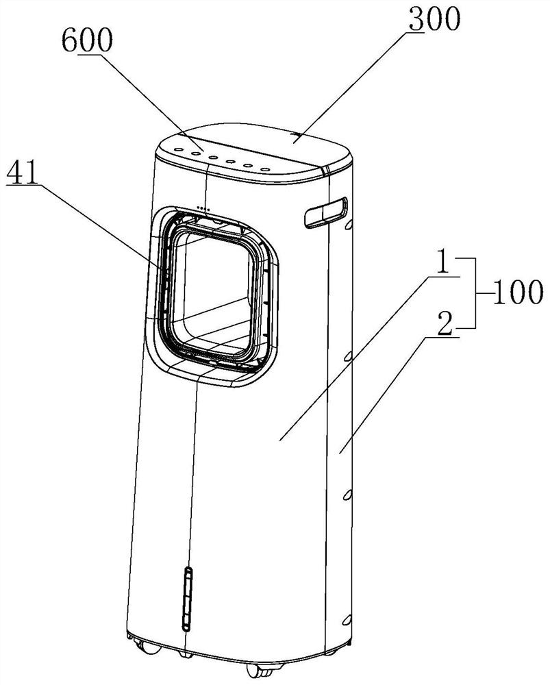
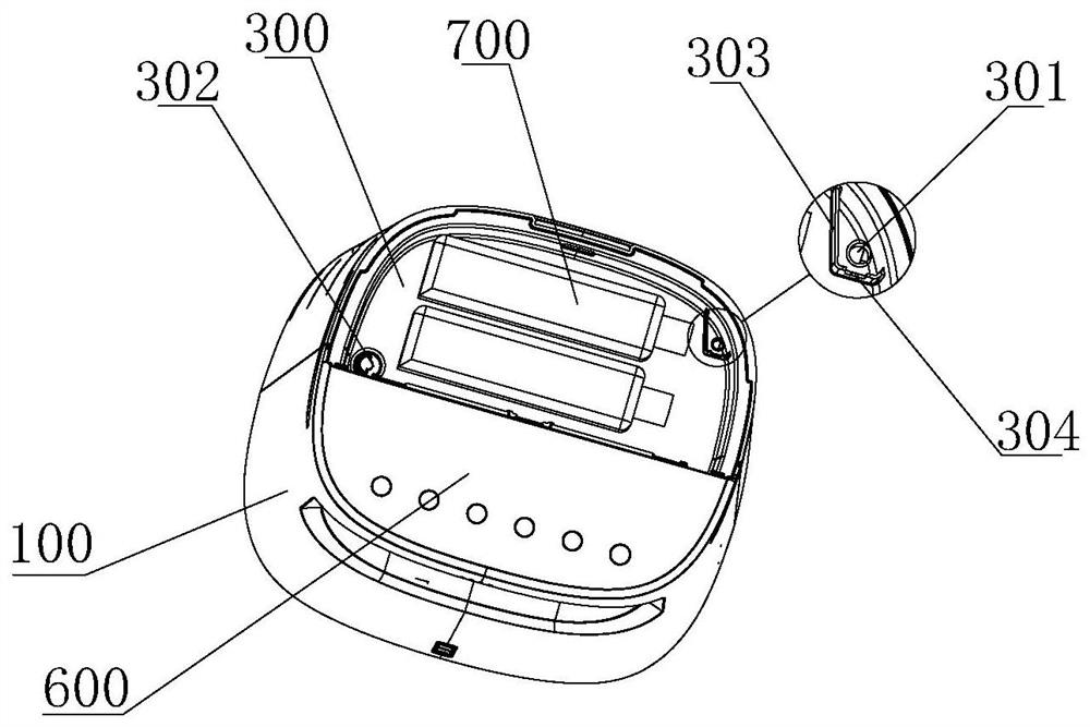
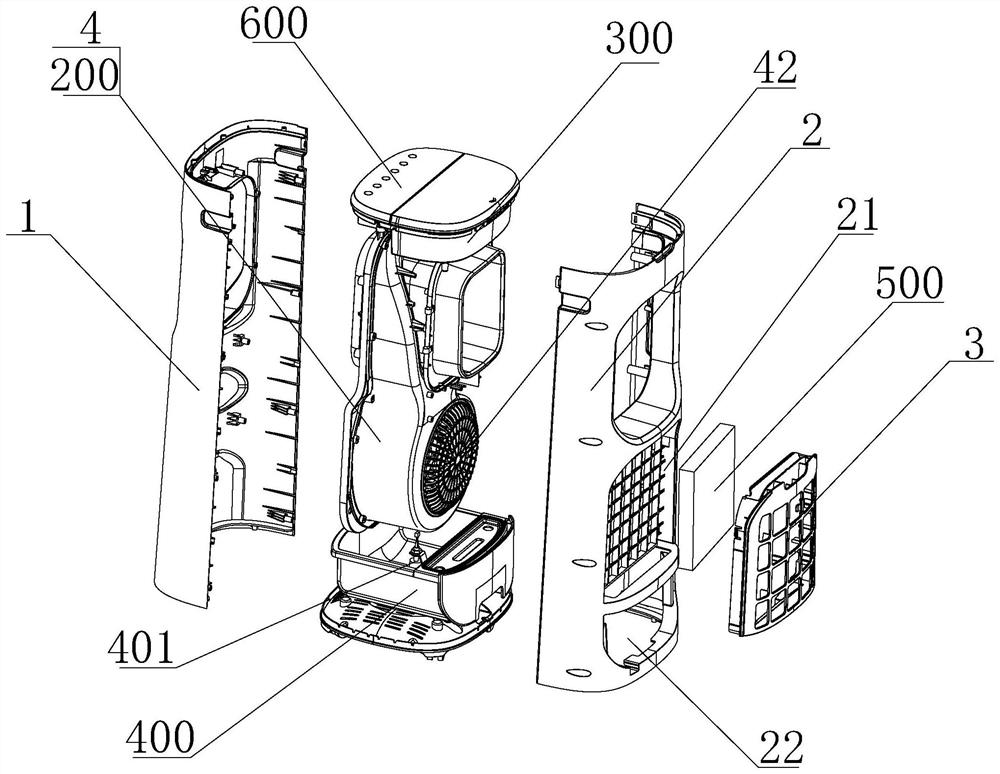
[0024] A novel bladeless air-conditioning fan of the present invention such as Figure 1 to Figure 5 As shown, it includes a casing 100, an air duct assembly 200, an upper water tank 300, a lower water tank 400, a control panel 600 and an ice curtain 500; wherein, the casing 100 is formed by combining the front casing 1 and the rear casing 2 and winds The channel assembly 200, the upper water tank 300, the lower water tank 400 and the control panel 600 are clamped between the front housing 1 and the rear housing 2, the control panel 600 and the upper water tank 300 are installed on the top of the shell 100, the control panel 600 and the upper The flip cover of the water tank 300 is combined to form the top wall of the casi...


PUM


Abstract

The invention discloses a novel bladeless air conditioner fan which comprises an air duct assembly, an upper water tank, a lower water tank and an ice curtain. The air duct assembly comprises an air duct shell and a draught fan, the air duct shell is provided with an air inlet and an air outlet, and the draught fan is correspondingly installed at the air inlet. The upper water tank is installed above the air duct assembly, the ice curtain is located below the upper water tank and correspondingly installed on the outer side of the air inlet of the air duct shell, and the upper water tank supplies water to the ice curtain through a lower water pipe. The lower water tank is correspondingly installed below the ice curtain and used for receiving water flowing down from the ice curtain, an upperwater pipe is connected between the lower water tank and the upper water tank, and an upper water pump is arranged on a pipeline of the upper water pipe. By the adoption of the upper water tank arranged on the upper portion, water can be added conveniently, an ice crystal box can be placed conveniently, and therefore cooling capacity generated by the ice crystal box can be brought to the positionof the ice curtain more easily and more rapidly through water, reaches the ice curtain more rapidly and is brought to the air outlet through the draught fan, and cold air making a user feel more comfortable is generated.

Description

technical field [0001] The invention relates to the technical field of fans, in particular to a novel bladeless air-conditioning fan. Background technique [0002] With the development of air-conditioning fan technology, various forms of air-conditioning fans have appeared in the prior art. Generally, the water path of air-conditioning fans is directly supplied by the water pump to the position of the ice curtain. Due to the high design difficulty and the corresponding increase in cost, There are very few air-conditioning fans that supply water from the water pump to the upper water tank. For bladeless air-conditioning fans, there is no such type of machine. Some machines with an upper water tank or models that add water to the upper water tank are only used for adding water alone, and cannot Store the ice crystal box in the upper water tank to realize the slow release function of the cooling capacity. It is still very troublesome for the user to use. The drawer must be pull...

Claims


Application Information

Patent Timeline
Patent Type & Authority Applications(China)
IPC IPC(8): F24F5/00F24F13/20
CPCF24F5/0017F24F13/20Y02E60/14
Inventor 丁正波李雄敏苗俊杰陈宇
Owner NINGBO AQUART ELECTRICAL APPLIANCE CO LTD
Why Eureka
Try Eureka