
Automatic door opening measuring equipment

An automatic measurement and equipment technology, applied in the field of door opening measurement, can solve the problems of large door opening specifications and dimensions, inconvenient operation, reducing the actual efficiency of construction and installation, and achieve the effect of complete functions and simple operation.

Active Publication Date: 2020-11-03
GUANGXI FUMEIYAO ENERGY SAVING WINDOWS & DOORS
View PDF9 Cites 0 Cited by
  • Summary
  • Abstract
  • Description
  • Claims
  • Application Information

AI Technical Summary

Problems solved by technology

[0004] The purpose of the invention is to provide an automatic measuring device for door openings to solve the problems in the above-mentioned background technology that because some door openings have large specifications and sizes, manual measurement requires the use of auxiliary tools to cooperate, which is very inconvenient to operate, and manual measurement Basically, through human observation, it is easy to have certain errors, which will affect the actual accuracy of the construction and installation of the door body, and greatly reduce the actual efficiency of construction and installation.

Method used


Image

  • Automatic door opening measuring equipment
  • Automatic door opening measuring equipment
  • Automatic door opening measuring equipment

Examples


Embodiment 1

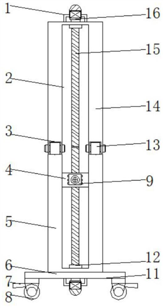
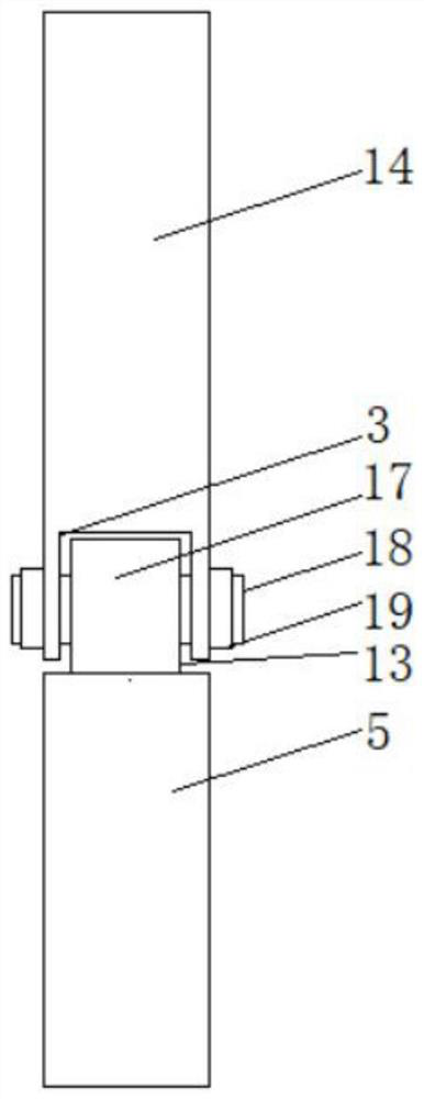
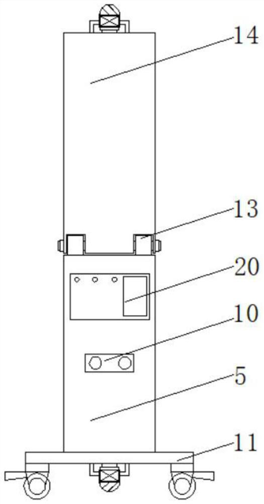
[0025] see Figure 1-3 , the invention provides a technical solution: an automatic measuring device for door openings, including a fixed base plate 5, both sides of the top of the fixed base plate 5 are installed with a movable plate 14 through the adjustment of the connecting assembly 13, and the inner sides of the fixed base plate 5 and the movable plate 14 are both A limit chute 2 is set up, the inside of the limit chute 2 is rotated by a rotating shaft 12 and a drive rod 15 is installed, and the surface thread of the drive rod 15 on the inside of the fixed bottom plate 5 is movably socketed with a slider 4, and the outside of the slider 4 is fixed and installed There is an infrared rangefinder 9, which drives the driving rod 15 to rotate in real time by starting the motor 16, and drives the slider 4 to move up and down through the thread twisting on the driving rod 15, and the driving rod 15 inside the movable plate 14 and the fixed base plate 5 The drive rod 15 on the inn...

Embodiment 2

[0030] In addition to the above solutions, the infrared range finder 9 has other methods, which can be set as a cube or a rhombus-shaped infrared light source cover 93, and one side edge is fixed on the base 91, so that the diagonal edge faces straight ahead. The edges and corners on both sides face both sides, and the entire infrared light source cover 93 is made of light-shielding material, and light-transmitting seams are arranged on the edges, and a focuser can also be added on the light source, so that the intensity of infrared rays increases, and the light can also be more concentrated .

[0031]Working principle: When it is necessary to measure the door opening, the whole device can be moved to any measurement location in real time through the universal wheel 8 first, and the whole device can be fixed by the brake 7 to avoid the need for manual handling, and then according to the actual door opening According to the requirements of different specifications and sizes, th...


PUM

PropertyMeasurementUnit
Thicknessaaaaaaaaaa
Widthaaaaaaaaaa

Abstract

The automatic door opening measuring equipment comprises a fixed bottom plate, movable plates are rotationally installed on the two sides of the top of the fixed bottom plate through adjusting connecting assemblies, and limiting sliding grooves are formed in the inner side of the fixed bottom plate and the inner sides of the movable plates. According to the automatic door opening measuring equipment, the movable plate can be manually pushed to enable the inserting rod to rotate according to the requirements of different specifications and sizes of actual door openings, so that the rotating block can rotate on the inner side of the rotating groove in real time, the position of the movable plate can be adjusted in real time, and the movable plate and the fixed bottom plate are in a verticalor vertical state; a motor is started to drive a driving rod to rotate in real time, a thread on the driving rod is twisted to drive a sliding block to move up and down in a reciprocating mode, the driving rod on the inner side of a movable plate is connected with the driving rod on the inner side of a fixed bottom plate, transition of the sliding block is achieved, the measurement stroke is prolonged, and therefore real-time scanning measurement is conducted through an infrared range finder. The operation is simpler and more efficient; and the measurement precision is higher.

Description

technical field [0001] The invention relates to the technical field of door opening measurement, in particular to an automatic door opening measurement device. Background technique [0002] Door openings generally refer to "roofed, long, hole-like aisles" inside the doors of large buildings such as city walls and mansions. In colloquial terms, they generally refer to the gates of houses. Door openings need to be carried out when building and installing the door body. Measurements are generally carried out on-the-spot by manual hand-held measuring rulers. [0003] However, due to the large specifications and sizes of some door openings, manual measurement requires the use of auxiliary tools to cooperate, which is very inconvenient to operate, and manual measurement is basically through human observation, which is prone to certain errors, which will affect the construction and installation of the door body. The actual accuracy greatly reduces the actual efficiency of construc...

Claims


Application Information

Patent Timeline
IPC IPC(8): G01B11/06G01B11/02G01C3/00G01C3/02
CPCG01B11/06G01B11/02G01C3/00G01C3/02
Inventor 韦玉香梁聪李智远韦建鹏覃小明黄波
Owner GUANGXI FUMEIYAO ENERGY SAVING WINDOWS & DOORS
Learn More