Portable soil sampler for construction

A technology for construction and soil fetching, applied in the direction of sampling devices, etc., can solve the problems of soil detection and detailed sampling, etc., and achieve the effect of being convenient for field detection and sampling, easy to expand, easy to carry and easy to install

Pending Publication Date: 2020-11-03
王跃峰
View PDF10 Cites 0 Cited by
  • Summary
  • Abstract
  • Description
  • Claims
  • Application Information

AI Technical Summary

Problems solved by technology

However, this equipment cannot automatically detect the depth of the position to be sampled

Method used


Image

  • Portable soil sampler for construction
  • Portable soil sampler for construction
  • Portable soil sampler for construction

Examples


specific Embodiment approach 1

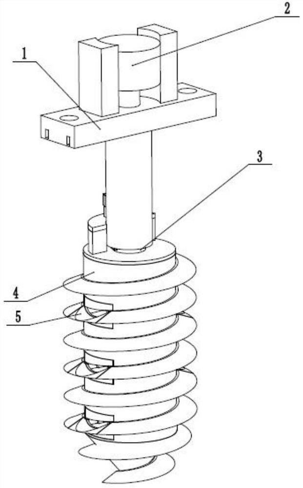
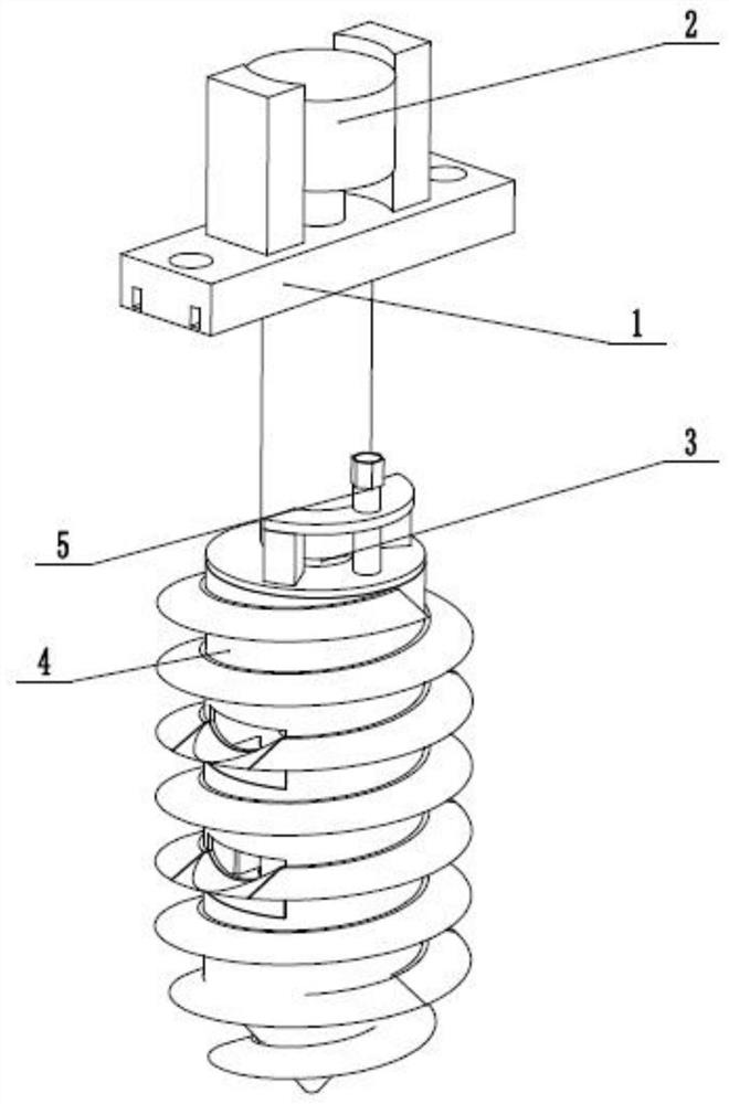
[0030] like Figure 1 to Figure 10 As shown, the portable soil fetcher for construction includes soil fetching holder 1, drilling driver 2, driving threaded sleeve 3, drilling threaded barrel 4 and layered soil sampler 5, and described drilling driver 2 is fixedly connected to On the soil-taking fixed seat 1, the inner end of the driving threaded sleeve 3 is longitudinally slidably connected in the hole-drilling driver 2, and the outer end of the driving threaded sleeve 3 is connected in the soil-taking fixed seat 1 through thread fit, and the driving threaded sleeve 3 is fixedly connected. On the threaded barrel 4 of the borehole, the layered soil sampler 5 is slidably connected in the threaded barrel 4 of the borehole. After selecting the designated location to be sampled, fix the soil-taking holder 1 through the insert plate and bolts, connect the hole-drilling driver 2 to the electric drive, and the hole-drilling driver 2 drives the threaded sleeve 3 to drive the drilling ...

specific Embodiment approach 2

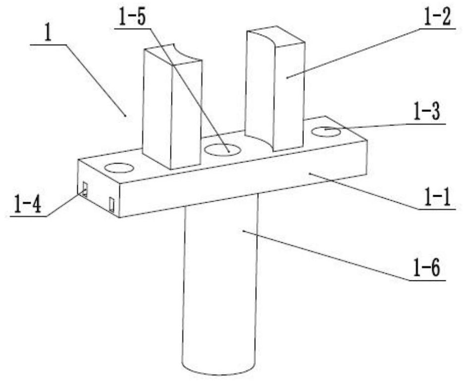
[0032] like Figure 1 to Figure 10As shown, this embodiment will further explain Embodiment 1. The soil-absorbing fixing base 1 includes a fixing platform 1-1, two motor fixing bases 1-2, two threaded fixing holes 1-3, and a horizontal fixing slot 1-4. Motor shaft rotation hole 1-5 and internal thread fixing sleeve 1-6, the upper end of fixing table 1-1 is fixedly connected with two motor fixing seats 1-2, and two threaded fixing holes 1-3 penetrate longitudinally respectively It is arranged on both sides of the fixed table 1-1, and both ends of the fixed table 1-1 are provided with a plurality of horizontal fixed slots 1-4, and the motor shaft rotation hole 1-5 is arranged at the middle end of the fixed table 1-1. The internal thread fixing sleeve 1-6 is fixedly connected to the center of the lower end of the fixing table 1-1. After selecting the specified position, fix the fixed table 1-1 by connecting the two threaded fixing holes 1-3 with bolts, or according to the actual...

specific Embodiment approach 3

[0034] like Figure 1 to Figure 10 As shown, this embodiment will further illustrate the second embodiment. The described hole driver 2 includes a drive motor 2-1, a drive extension shaft 2-2 and four longitudinal T-shaped chutes 2-3, and the drive motor 2- 1. It is fixedly connected between the two motor fixing seats 1-2. The transmission shaft of the driving motor 2-1 is rotatably connected in the circular hole 1-5 of the motor shaft. The upper end of the driving extension shaft 2-2 is connected to drive through a coupling The transmission shaft of the motor 2-1, four longitudinal T-shaped chutes 2-3 are evenly arranged on the drive extension rotating shaft 2-2. The drive motor 2-1 is powered forward and rotates, driving the extension rotating shaft 2-2 to rotate.


PUM


Abstract

The invention relates to the field of construction tools, in particular to a portable soil sampler for construction, which comprises a soil sampling fixing seat, a hole drilling driver, a driving threaded sleeve, a hole drilling threaded cylinder and a stratified soil sampler; the hole drilling driver is fixedly connected to the soil sampling fixing seat, and the inner end of the driving threadedsleeve is longitudinally connected into the hole drilling driver in a sliding manner; the outer end of the driving threaded sleeve is connected into the soil sampling fixing base in a threaded fit mode, the driving threaded sleeve is fixedly connected to the drilling threaded cylinder, and the stratified soil sampler is connected into the drilling threaded cylinder in a sliding mode; the soil sampler has the beneficial effects that drilling and holing can be automatically carried out on the position of soil to be sampled; transverse depth soil sampling can be carried out on soil with differentdepths after hole digging, the sampling range of soil sampling can be expanded conveniently, and sampling and transverse and longitudinal comparison are carried out on deep soil; the portable soil sampler is very convenient to carry and install, and is convenient for field detection and sampling.

Description

technical field [0001] The invention relates to the field of construction tools, in particular to a portable soil fetcher for construction. Background technique [0002] Patent No. CN201711011474.6 discloses a portable soil fetcher for construction, which belongs to construction equipment. It includes a cross bar; the upper end of the cross bar is symmetrically provided with two first rotating shafts; the first movable rod is fixedly connected to the first rotating shaft; the upper end of the first movable rod is provided with a sleeve; the two ends of the cross bar There is a second rotating shaft fixed at the bottom; a connecting rod is fixed at the lower end of the second rotating shaft; an L-shaped block is fixed at the lower left end of the connecting rod; a block is vertically arranged at the right end of the L-shaped block; the right end of the connecting rod The limit block is fixed horizontally; a spring is connected between the left end of the fixed block and the ...

Claims


Application Information

Patent Timeline
IPC IPC(8): G01N1/08
CPCG01N1/08
Inventor 王跃峰
Owner 王跃峰
Why Eureka
Try Eureka