
Pulse wave velocity correction method for partial discharge monitoring of high-voltage cable

A partial discharge monitoring and correction method technology, which is applied in the direction of voltage/current isolation, measuring electricity, measuring devices, etc., can solve the problems of different wave velocities, pulse wave velocities cannot be obtained accurately, and accuracy depends on propagation speed, etc., to achieve accurate positioning.

Active Publication Date: 2020-11-03
STATE GRID CHONGQING ELECTRIC POWER CO ELECTRIC POWER RES INST +2
View PDF12 Cites 0 Cited by
  • Summary
  • Abstract
  • Description
  • Claims
  • Application Information

AI Technical Summary

Problems solved by technology

[0003] The accuracy of locating cable defects through partial discharge is very dependent on the propagation speed of the discharge signal in the cable. At present, the pulse wave velocity cannot be accurately obtained in cable partial discharge monitoring, and 172m / μs is often used for related calculations.
However, the wave velocity of the pulse in the cable is affected by the temperature of the medium, so the wave velocity is often different at different times due to the load fluctuation of the cable.

Method used


Image

  • Pulse wave velocity correction method for partial discharge monitoring of high-voltage cable
  • Pulse wave velocity correction method for partial discharge monitoring of high-voltage cable
  • Pulse wave velocity correction method for partial discharge monitoring of high-voltage cable

Examples


Embodiment Construction

[0038] The present invention will be further described below in conjunction with drawings and embodiments.

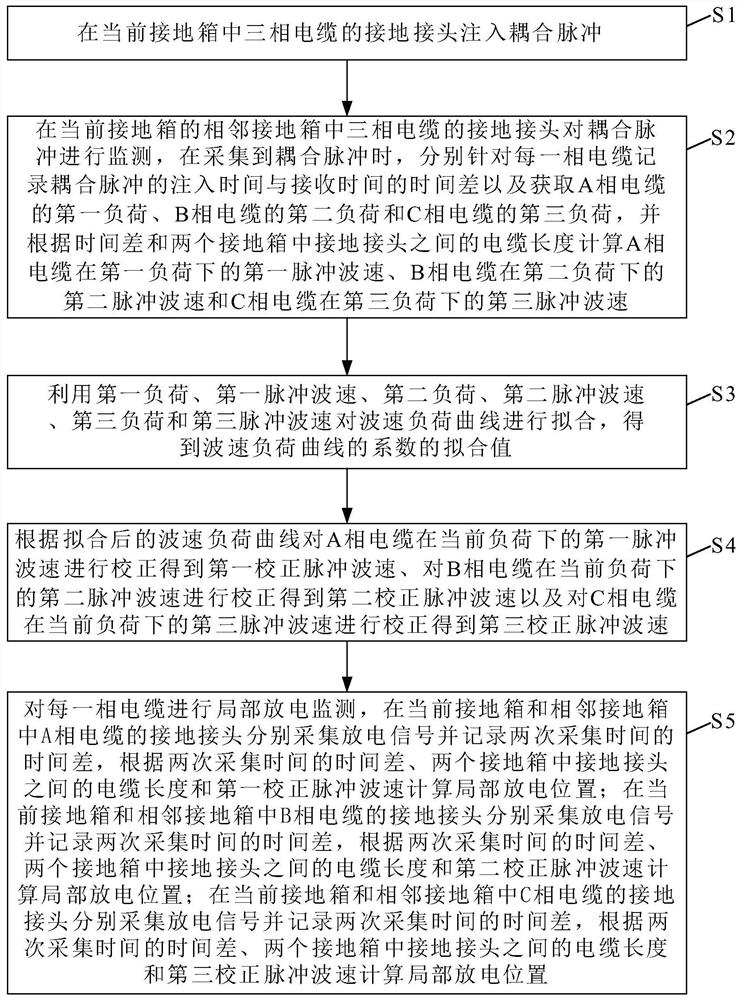
[0039] Examples such as figure 1 Shown; A kind of pulse velocity correction method that is used for high-voltage cable partial discharge monitoring, it comprises the following steps:

[0040] S1: Inject coupled pulses at the grounding joint of the three-phase cable in the current grounding box.

[0041] In particular, the coupled pulses can be injected through a pulse coupling device. The pulse coupler is installed on the cable at the ground connection.

[0042] S2: Monitor the coupling pulse at the ground joint of the three-phase cable in the adjacent grounding box of the current grounding box. When the coupling pulse is collected, record the time difference between the injection time and the receiving time of the coupling pulse for each phase cable and obtain The first load of the A-phase cable, the second load of the B-phase cable and the third load of the C-phase...


PUM


Abstract

The invention discloses a pulse wave velocity correction method for partial discharge monitoring of a high-voltage cable, and the method comprises the steps: firstly injecting a coupling pulse into agrounding connector of a three-phase cable in a current grounding box based on electromagnetic coupling, and then collecting the coupling pulse at the grounding connector of the three-phase cable in an adjacent grounding box of the current grounding box; calculating the pulse wave velocity according to the length of the cable and the coupling pulse transmission time, fitting the load of the three-phase cable and the coefficient of the pulse wave velocity to the wave velocity load curve, and finally correcting the pulse wave velocity under the real-time load through the fitted wave velocity load curve to obtain the corrected pulse wave velocity. The correction pulse wave velocity is used for partial discharge positioning, so that the positioning result is more accurate. The pulse wave velocity can be accurately corrected according to load fluctuation, and accurate positioning of the partial discharge position is facilitated.

Description

technical field [0001] The invention relates to the technical field of cable insulation detection, in particular to a pulse wave velocity correction method for partial discharge monitoring of high-voltage cables. Background technique [0002] High-voltage cable partial discharge monitoring is of great significance for the early detection of cable insulation defects. At present, high-voltage cable partial discharge monitoring usually installs a high-frequency current transformer (HFCT) at the cross-connection grounding box to collect partial discharge signals, and conducts different signals through optical fibers. Time base synchronization of acquisition points. [0003] The accuracy of locating cable defects through partial discharge is very dependent on the propagation speed of the discharge signal in the cable. At present, the pulse wave velocity cannot be accurately obtained in cable partial discharge monitoring, and 172m / μs is often used for related calculations. Howeve...

Claims


Application Information

Patent Timeline
IPC IPC(8): G01R31/12G01R31/08G01R15/18
CPCG01R31/1272G01R31/083G01R15/18Y04S10/52
Inventor 何维晟吴照国邓帮飞向洪张海兵王谦黄会贤
Owner STATE GRID CHONGQING ELECTRIC POWER CO ELECTRIC POWER RES INST
Learn More