Axial flux permanent magnet motor for high voltage circuit breaker and its use

A high-voltage circuit breaker and axial magnetic flux technology, applied in the direction of magnetic circuits, electric components, electromechanical devices, etc., can solve the problem of affecting the opening and closing control effect of circuit breakers, reducing the servo performance of the motor operating mechanism, and unable to further improve the output Torque and other issues, to achieve the effect of improving dynamic response, increasing output torque, and increasing voltage level

Active Publication Date: 2021-10-26
TSINGHUA UNIV
View PDF3 Cites 0 Cited by
  • Summary
  • Abstract
  • Description
  • Claims
  • Application Information

AI Technical Summary

Problems solved by technology

[0008] Tsinghua University adopts inner rotor permanent magnet synchronous motor with radial magnetic field, and the 126kV motor-driven high-voltage circuit breaker developed by Tsinghua University was put into operation in the Southern Power Grid in 2016, but the applied voltage level has been difficult to further improve
[0009] Since the linear motor directly drives the load, changes in the load and external disturbances will be reflected on the mover without attenuation, and the motor has a large longitudinal end effect and cogging effect, and the thrust ripple generated will directly reduce the motor operation. The servo performance of the mechanism, especially in high-precision control occasions, affects the control effect of the opening and closing of the circuit breaker
[0010] The magnetic flux path at the root of the rotor in the radial field motor is bottleneck-like, and it is easy to saturate, so the output torque cannot be further improved, and there are also disadvantages such as difficult cooling and low utilization of the rotor core.

Method used


Image

  • Axial flux permanent magnet motor for high voltage circuit breaker and its use
  • Axial flux permanent magnet motor for high voltage circuit breaker and its use
  • Axial flux permanent magnet motor for high voltage circuit breaker and its use

Examples


Embodiment Construction

[0042] In order to make the object, technical solution and advantages of the present invention clearer, the present invention will be further described in detail below in combination with specific embodiments and with reference to the accompanying drawings. It should be understood that these descriptions are exemplary only, and are not intended to limit the scope of the present invention. Also, in the following description, descriptions of well-known structures and techniques are omitted to avoid unnecessarily obscuring the concept of the present invention.

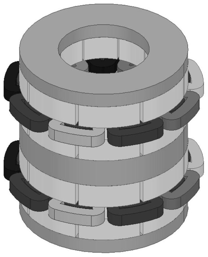
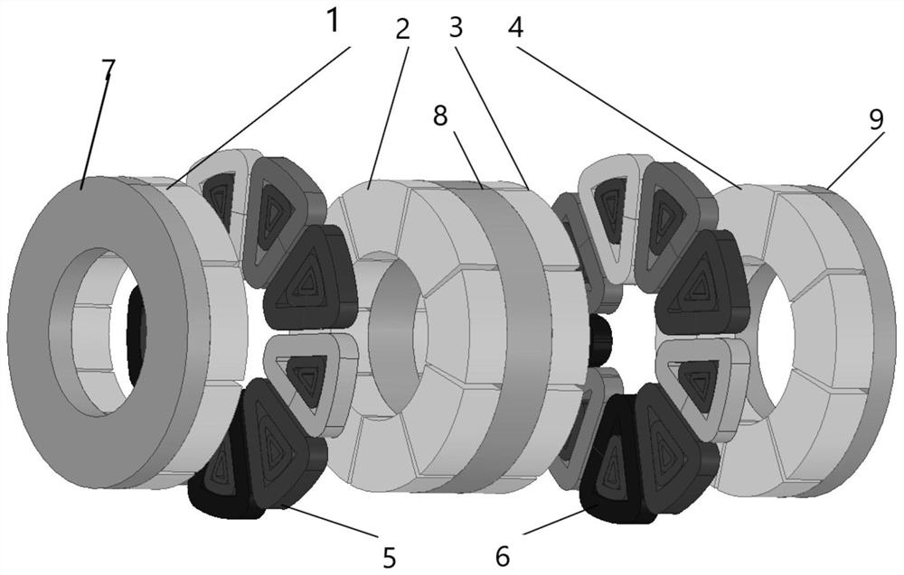
[0043] The invention adopts the axial magnetic flux permanent magnet synchronous motor to improve the dynamic response performance of the drive motor of the voltage circuit breaker. The motor adopts a sandwich structure with three stators and two rotors, including the following structures: brushless winding rotor, permanent magnet stator.

[0044] combine Figure 1-2 , the axial flux permanent magnet synchronous motor i...


PUM


Abstract

The invention relates to an axial flux permanent magnet motor used for a high-voltage circuit breaker and its use, comprising a first stator, a first rotor, a second stator, a second rotor and a third stator arranged in sequence along the axial direction, A sandwich structure with three stators and two rotors is formed; iron cores are arranged on the outside of the first stator and the third stator; the second stator is a double-layer structure, and an iron core is arranged in the middle; the first rotor and the second rotor have the same structure, Both include nine brushless windings of three phases arranged in the circumferential direction, the nine brushless windings form a ring, and a magnetic field is generated during rotation. The invention adopts the axial magnetic field permanent magnet synchronous motor as the driving motor of the high-voltage circuit breaker, which reduces the saturation degree of the iron core, thus increases the output torque and reduces the moment of inertia, and further improves the voltage level of the high-voltage circuit breaker driven by the motor. The fixed material density of the winding is relatively low, which can improve the dynamic response of the motor-driven high-voltage circuit breaker.

Description

technical field [0001] The invention relates to the technical field of motors, in particular to an axial flux permanent magnet motor used for a high-voltage circuit breaker and its use. Background technique [0002] The main function of the high-voltage circuit breaker is reflected in the opening and closing operation of the moving contact, and the opening and closing operation is realized through the operating mechanism. At present, the commonly used operating mechanisms mainly include electromagnetic operating mechanisms, spring operating mechanisms, pneumatic operating mechanisms and hydraulic operating mechanisms. These traditional control mechanisms have relatively large deficiencies, which are reflected in poor flexibility, large dispersion of action time, unfavorable production and maintenance, and low reliability. In addition, under the requirements of the current high-speed development of the smart grid, it is also required to monitor key parameters such as the mec...

Claims


Application Information

Patent Timeline
Patent Type & Authority Patents(China)
IPC IPC(8): H02K16/00H02K3/28H02K1/17H02K3/51
CPCH02K1/17H02K3/28H02K3/51H02K16/00H02K2201/12
Inventor 肖曦周家玥
Owner TSINGHUA UNIV
Why Eureka
Try Eureka