Oxygen flow monitoring device

A monitoring device and oxygen flow technology, applied in the field of medical devices, can solve the problems of short service life, inability to classify monitoring, oxygen supply interruption, etc., and achieve the effect of reducing procurement costs, reducing treatment costs, and avoiding oxygen supply interruptions.

Inactive Publication Date: 2020-11-06
THE FIRST PEOPLES HOSPITAL OF CHANGZHOU
View PDF0 Cites 0 Cited by
  • Summary
  • Abstract
  • Description
  • Claims
  • Application Information

AI Technical Summary

Problems solved by technology

[0003] Therefore, it is necessary to utilize an oxygen flow monitoring device to monitor the oxygen flow in the oxygen inhalation tube, but the oxygen flow monitoring device in the prior art cannot classify and monitor the flow of oxygen supplied by the oxygen mask and the flow of oxygen supplied by the nasal tube. Different devices are used to monitor the oxygen flow of different oxygen supply methods. In this case, the purchase cost of the hospital will be increased, and the treatment cost of the patient will also be increased. The fixing effect is not good, it is easy to fall off, and it will cause interruption of oxygen supply, it is difficult to effectively ensure safe oxygen supply for patients, it is easy to be damaged by vibration, it is not resistant to falling, and its service life is short

Method used


Image

  • Oxygen flow monitoring device
  • Oxygen flow monitoring device
  • Oxygen flow monitoring device

Examples


Embodiment 1

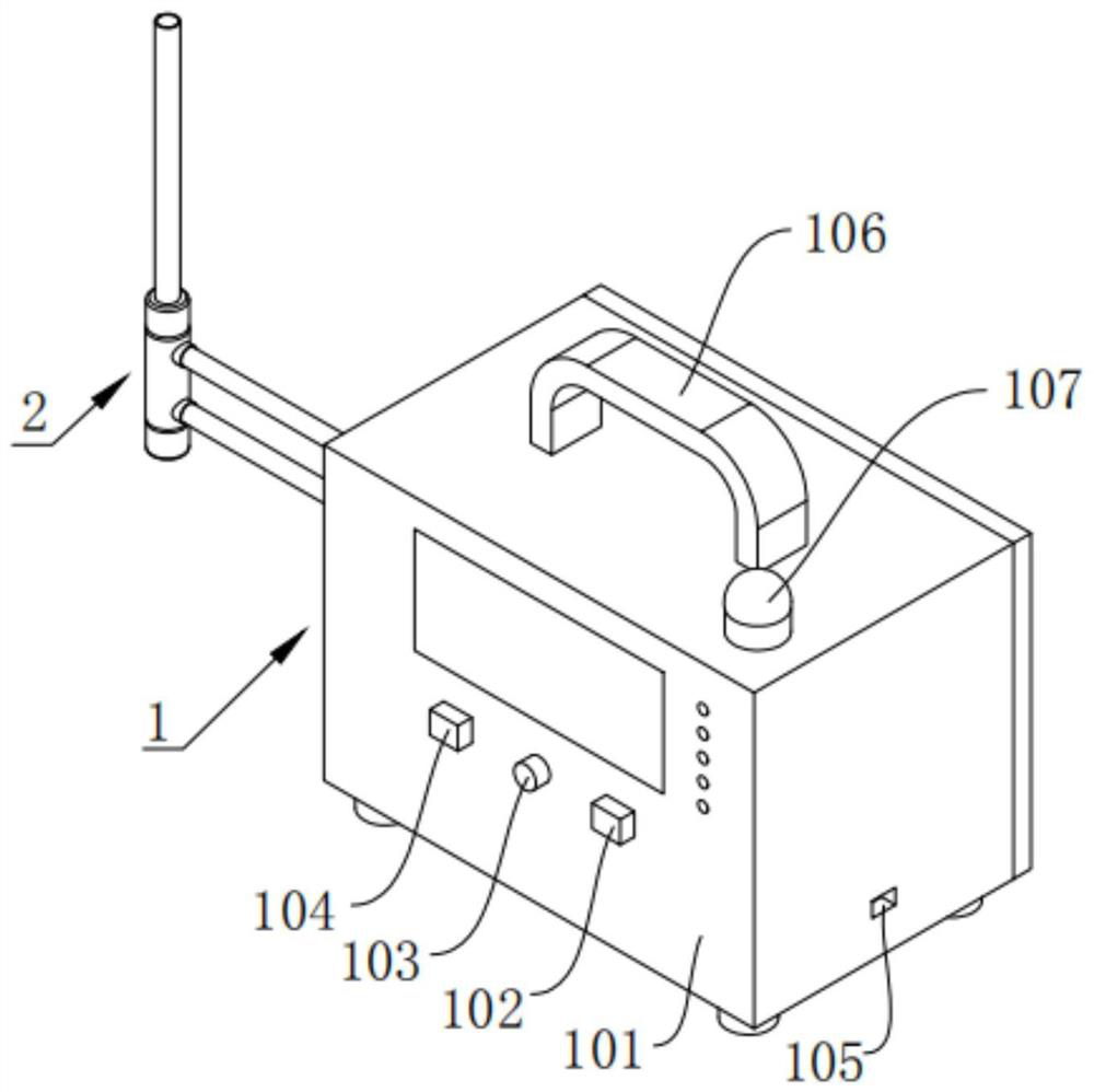
[0042] An oxygen flow monitoring device such as Figure 1-3 As shown in and 6-7, a monitoring mechanism 1 is included, and the monitoring mechanism 1 includes a housing 101, a display screen 109, a first oxygen supply mode selection button 102, a second oxygen supply mode selection button 104, a mounting plate 116, a horn 119, The controller 117 and the ultrasonic gas flowmeter 122, the first insertion tube 114 and the second insertion tube 115 are fixedly installed on one end wall of the housing 101, and the display screen 109 is embedded in the front part of the housing 101, so Both the first oxygen supply mode selection button 102 and the second oxygen supply mode selection button 104 are fixedly installed on the front part of the housing 101, and the mounting plate 116 is fixedly installed on the housing through two sets of fittings 3 101, the horn 119 and the controller 117 are fixedly mounted on the mounting plate 116, and the controller 117 is connected to the horn 119,...

Embodiment 2

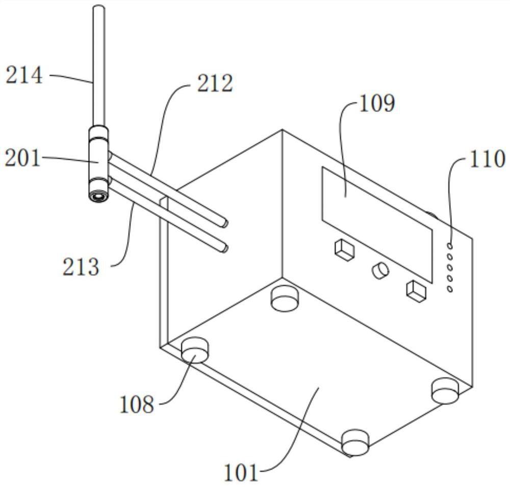
[0048] Such as Figure 1-5 As shown, the difference between this embodiment and Embodiment 1 is that it also includes a connection mechanism 2, and the connection mechanism 2 includes a cylindrical base 201, a first round tubular plug joint 204, a second round tubular plug joint 205, The first connecting pipe 213, the second connecting pipe 212 and the third connecting pipe 214, the two ends of the cylindrical base 201 are respectively provided with a first channel 202 and a second channel 203, and the cylindrical base 201 The two ends of both ends are uniformly provided with a tubular socket 207, and the outside of the circular tubular socket 207 is integrally provided with a circular tubular connecting seat 206, and the circular tubular connecting seat 206 faces away from the cylindrical base A notch 209 is provided on one end wall of the seat 201, and a locking sleeve 208 is screwed on the outside of the circular tubular connecting seat 206, and the first circular tubular p...

Embodiment 3

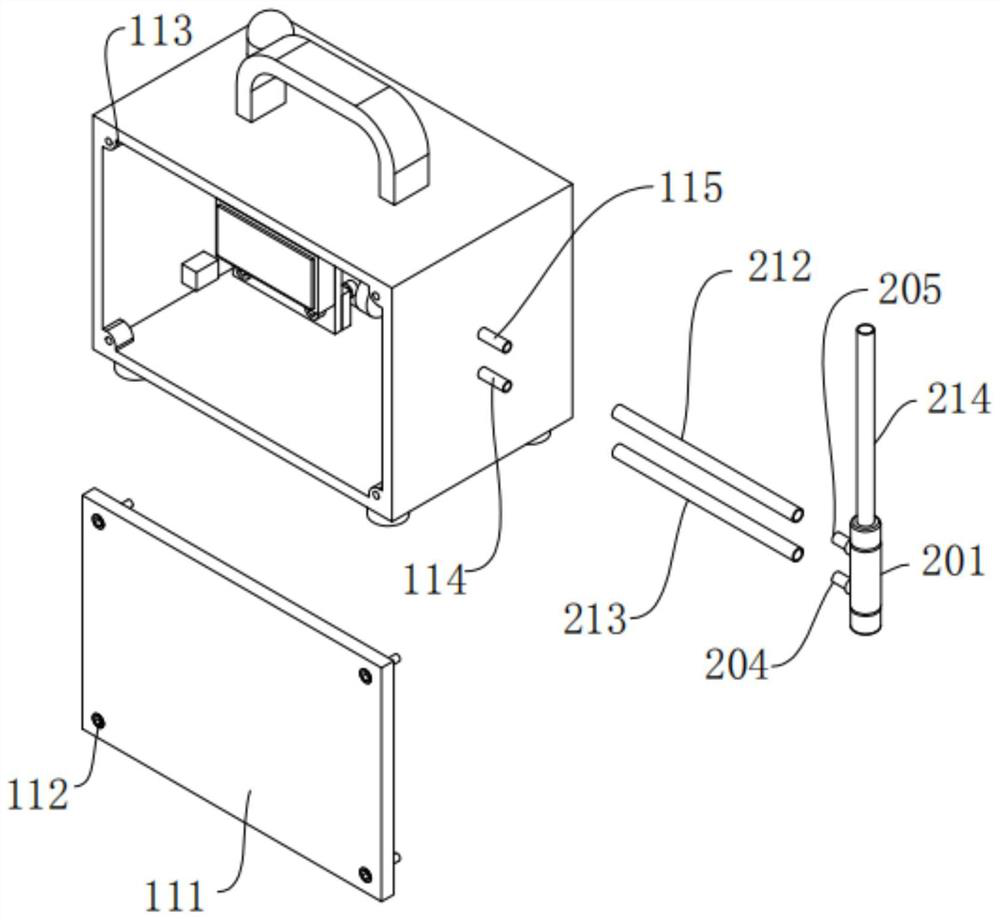
[0051] Such as image 3 , 6As shown in and 7, the difference between this embodiment and embodiment 2 is that: the rear part of the housing 101 is an open structure, and the rear part of the housing 101 is fixedly installed with a rear cover 111 by a third screw 112, And the rear part of the housing 101 is integrally provided with a mounting ear 113, and the inside of the mounting ear 113 is provided with a first threaded hole matching the third screw 112, and the rear cover 111 is far away from the housing. On one side of 101, a receiving groove for accommodating the third screw 112 is reserved, and the first screw 303, the second screw 118 and the third screw 112 are all hexagon socket head cap screws, and the Two second threaded holes 307 matched with the second screw 118 are also provided on the second fitting plate 304 adjacent to its two ends, and the diameter of the second threaded hole 307 is larger than the maximum diameter of the first screw 303. Further, the mount...


PUM


Abstract

The invention discloses an oxygen flow monitoring device. The device comprises a monitoring mechanism which comprises a shell, a display screen, a first oxygen supply mode selection button, a second oxygen supply mode selection button, a mounting plate, a loudspeaker, a controller and an ultrasonic gas flowmeter. According to the oxygen flow monitoring device disclosed by the invention, when it ismonitored that the oxygen flow in an oxygen pipe is abnormal, the controller controls the loudspeaker to give an alarm sound to inform medical staff to handle the abnormality of the oxygen flow in time, so that the danger of a patient caused by insufficient oxygen supply or excessive oxygen supply to the patient is avoided; the oxygen supply flow of an oxygen mask and the oxygen supply flow of anasal tube can be monitored in a classified mode, the purchase cost of a hospital can be reduced, and meanwhile, the disease treatment cost of a patient can be reduced; the fixing effect on a hose ofthe oxygen supply mask or the oxygen supply nasal tube of the oxygen tube is good, disengagement can be effectively prevented, and oxygen supply interruption is avoided; therefore, oxygen is effectively and safely supplied to the patient, damage caused by vibration is not prone to happening, falling resistance is achieved, and the service life is long.

Description

technical field [0001] The invention relates to the technical field of medical instruments, more specifically, it relates to an oxygen flow monitoring device. Background technique [0002] Oxygen inhalation tubes for clinical use often have no oxygen, or the oxygen tube is pressed, so that the oxygen flow cannot meet the requirements, which is very dangerous for patients. Now there are mainly two types of oxygen inhalation. Oxygen masks, one is a nasal tube, and the oxygen flow of the two methods is different. [0003] Therefore, it is necessary to utilize an oxygen flow monitoring device to monitor the oxygen flow in the oxygen inhalation tube, but the oxygen flow monitoring device in the prior art cannot classify and monitor the flow of oxygen supplied by the oxygen mask and the flow of oxygen supplied by the nasal tube. Different devices are used to monitor the oxygen flow of different oxygen supply methods. In this case, the purchase cost of the hospital will be increas...

Claims


Application Information

Patent Timeline
IPC IPC(8): A61M16/00C09D163/00C09D127/18C09D7/61C09D7/63C09D7/65C09D5/10C09D5/14
CPCA61M2016/0033A61M2205/18A61M2205/3334A61M16/0003C08K2003/0806C08K2003/2248C08K2003/265C08K2201/011C08L2201/08C08L2205/035C09D5/10C09D5/14C09D163/00C09D7/61C09D7/63C09D7/65C08L27/18C08L91/06C08L83/04C08K13/02C08K3/26C08K3/22C08K3/08C08K3/34C08K5/17
Inventor 姚海艳
Owner THE FIRST PEOPLES HOSPITAL OF CHANGZHOU
Why Eureka
Try Eureka