Bypass filtering system for filtering impurities in water

A technology of impurity and filter water tank, which is applied in the field of side filter system and can solve problems such as poor filtering effect

Active Publication Date: 2020-11-06
台嘉成都玻纤有限公司
View PDF26 Cites 4 Cited by
  • Summary
  • Abstract
  • Description
  • Claims
  • Application Information

AI Technical Summary

Problems solved by technology

[0004] The purpose of the present invention is to overcome the shortcomings of the side filter device in the prior art that is easy to deposit impurities after long-term use, resulting in poor filtering effect, and provides a side filter system for filtering impurities in water, including a filter tank and a sedimentation

Method used


Image

  • Bypass filtering system for filtering impurities in water
  • Bypass filtering system for filtering impurities in water
  • Bypass filtering system for filtering impurities in water

Examples


Embodiment 1

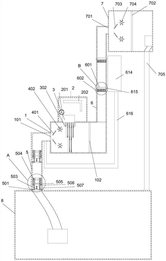
[0042] Such as figure 1 As shown, this embodiment includes a water filter box 1 and a sedimentation tank 2 arranged on the outer side wall of the water filter box 1. A first water inlet hole 101 is opened on the upper side wall of the water filter box 1, and a first water outlet is provided at the bottom of the water filter box 1. The water pipe 6 has a first through hole on the side wall of the filter tank 1, and a second through hole matched with the first through hole on the side wall of the sedimentation tank 2. One side of the water tank 1 is provided with a rotating shaft 3, and a foldable filter assembly is provided on the side wall of the rotating shaft 3. In the initial state, the filter assembly is located in the filter water tank 1, and the filter assembly is completely unfolded to block the cross section of the filter water tank 1. During use, the rotating shaft 3 rotates to drive the filter assembly through the first through hole and the second through hole, so th...

Embodiment 2

[0045] Such as figure 1 , 4 As shown in ~8, this embodiment also includes on the basis of Embodiment 1: the filter assembly includes a plurality of filter units made up of the first rotating cylinder 301 and the fan-shaped filter screen 302, and the end of the fan-shaped filter screen 302 is fixed on the first rotary drum. On the outer wall of the cylinder 301, a plurality of first rotating cylinders 301 are sleeved on the rotating shaft 3 along the axial direction of the rotating shaft 3. There is a third annular chute, a first telescopic rod is provided on the side wall of the rotating shaft 3, and a second slider that slides along the third annular chute is provided at the end of the first telescopic rod, along the circumferential direction of the rotating shaft 3 on its side External teeth 303 are arranged on the wall, and a toothed belt 304 cooperating with the external teeth 303 is provided on its inner wall along the circumference of the first drum 301. One end of the ...

Embodiment 3

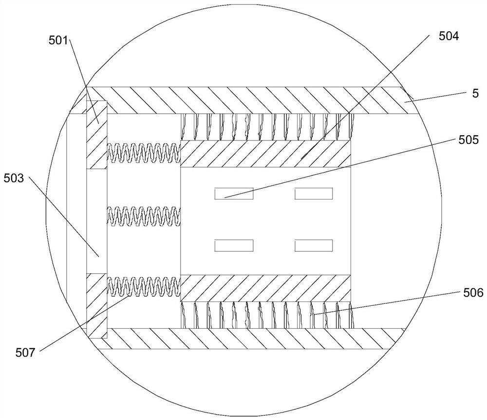
[0052] Such as Figure 1~2 As shown, on the basis of Embodiment 1, this embodiment also includes: a first water inlet pipe 5 communicating with it is provided on the upper side of the first water inlet hole 101, and on the inner side wall of the first water inlet pipe 5 along its circumference There are a plurality of first annular chutes distributed along the first water inlet pipe 5, and along the axial direction of the first water inlet pipe 5, there are a plurality of rotating plates 501 that cooperate with the first annular chute one by one. A third through hole 503 is opened on the top, and a second drum 504 matching the rotating plate 501 is provided on the side of any rotating plate 501 close to the filter tank 1 along the axial direction of the first water inlet pipe 5. The rotating plate 501 and the second rotating drum 504 are connected by a plurality of second springs 507, the two ends of the second rotating drum 504 are open, and a plurality of first springs for d...


PUM


Abstract

The invention discloses a bypass filtration system for filtering impurities in water. The bypass filtration system comprises a water filtering tank and a settling tank arranged on the outer side wallof the water filtering tank, wherein a first water inlet hole is formed in the upper side wall of the water filtering tank, a first water outlet pipe is arranged at the bottom of the water filtering tank, a first through hole is formed in the side wall of the water filtering tank, a second through hole matched with the first through hole is formed in the side wall of the settling tank, a rotatingshaft is arranged on one side, close to the water filtering tank, of the settling tank in the vertical horizontal direction, a foldable filtering assembly is arranged on the side wall of the rotatingshaft, the filtering assembly is located in the water filtering tank in the initial state, the filtering assembly is completely unfolded and blocks the cross section of the water filtering tank, and the part, located in the water filtering tank, of the filtering assembly is folded in the direction close to the settling tank in use. Compared with the prior art, the bypass filtering system providedby the invention has the advantages that by arranging the foldable filtering assembly, impurities deposited on the filtering assembly are transferred into the settling tank, so that the impurities areprevented from being deposited on the filtering assembly to influence the filtering effect.

Description

technical field [0001] The invention relates to a side filter system, in particular to a side filter system for filtering impurities in water. Background technique [0002] At present, the heat generated during the operation of equipment in industrial production is mainly cooled by circulating water. During the operation of the circulating water system, especially in the cooling water, there will be a large amount of suspended matter, which seriously affects the heat transfer function. Among them, due to the entry of dust and debris in the air, some scale, rust, and microbial slime will fall off and disperse after daily cooling treatment, which will cause water quality to be turbid. Due to the low solubility of various impurities in water, a bypass quartz sand filter is generally installed on the system pipeline for filtration. Side filtration is not to install the filter on the general circulation pipeline to filter all the circulating water once, but to lead a part of the...

Claims


Application Information

Patent Timeline
IPC IPC(8): B01D36/04C02F9/02
CPCB01D36/04C02F1/001C02F1/52C02F2201/002C02F2201/004C02F2201/005C02F2301/08C02F2303/16C02F2303/14
Inventor 林嘉佑
Owner 台嘉成都玻纤有限公司
Why Eureka
Try Eureka