Power head

A power head and movable ground technology, which is applied in the direction of driving devices, metal processing machinery parts, metal processing equipment, etc., can solve the problem of external power head, etc., and achieve the effect of small inertial force, strong bearing capacity and sensitive action

Pending Publication Date: 2020-11-06
福建旺鼎科技有限公司
View PDF0 Cites 2 Cited by
  • Summary
  • Abstract
  • Description
  • Claims
  • Application Information

AI Technical Summary

Problems solved by technology

[0004] The present invention aims to provide a power head to solve the problem that the feeding mechanism of the power head is placed outside

Method used


Image

  • Power head
  • Power head
  • Power head

Examples


Embodiment Construction

[0029] To further illustrate the various embodiments, the present invention is provided with accompanying drawings. These drawings are a part of the disclosure of the present invention, which are mainly used to illustrate the embodiments, and can be combined with related descriptions in the specification to explain the operating principles of the embodiments. With reference to these contents, those skilled in the art should understand other possible implementations and advantages of the present invention. Components in the figures are not drawn to scale, and similar component symbols are generally used to denote similar components.

[0030] The present invention will be further described in conjunction with the accompanying drawings and specific embodiments.

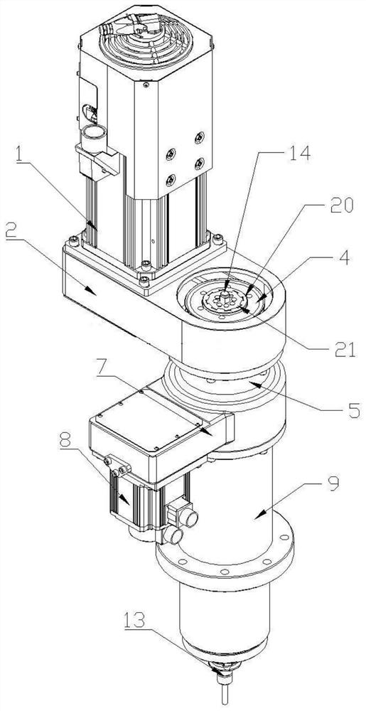
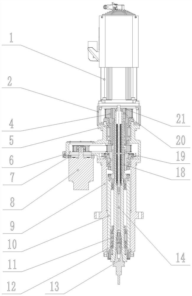
[0031] combine figure 1 and figure 2 As shown, this embodiment provides a power head, defining the end of the power head for connecting to the tool holder as the lower end, the power head includes a vertically downwa...


PUM


Abstract

The invention provides a power head. The power head comprises a feeding motor, a main shaft shell, a main shaft gun barrel and a main shaft, wherein the main shaft gun barrel is arranged on the main shaft in a sleeving manner and can be axially and movably inserted in the main shaft shell; the feeding motor is fixed to the main shaft shell; the power head further comprises a gun barrel lead screwand a feeding nut; the gun barrel lead screw is arranged on the main shaft gun barrel and arranged in a gun barrel shell; the feeding nut can be rotationally arranged in the main shaft shell and is arranged on the gun barrel lead screw in a sleeving manner; and the feeding motor is in transmission connection with the feeding nut. According to the power head, the gun barrel lead screw is arranged on the main shaft gun barrel, then the feeding nut is arranged in the main shaft shell, the feeding motor drives the feeding nut to rotate, feeding components, namely the lead screw and the nut, of thepower head are coaxial with the main shaft, and the problem about external arrangement of a power head feeding mechanism is solved.

Description

technical field [0001] The invention belongs to the technical field of machining and manufacturing, and in particular relates to a power head for a machining center. Background technique [0002] In machining equipment, the power head is the core equipment that drives the spindle to rotate and feed, which affects machining accuracy and production efficiency. [0003] The power head in the prior art, the power feed generally comprises feed motor and screw nut assembly, and the output shaft of feed motor is provided with screw mandrel, and the cantilever mounting nut that protrudes out of the gun barrel casing is passed on the gun barrel, and then Realize feed adjustment. The power feeding mechanism of this kind of structure is all arranged on the outside of the gun barrel shell, and the overall power head seems bloated, takes up space, and affects the smoothness of transmission. Contents of the invention [0004] The present invention aims to provide a power head to solve...

Claims


Application Information

Patent Timeline
IPC IPC(8): B23Q5/04
CPCB23Q5/04
Inventor 林斌星陈德辉
Owner 福建旺鼎科技有限公司
Why Eureka
Try Eureka