White handle top end angle precision machining device and method for electric resistance welding
A processing device and resistance welding technology, applied in the direction of grinding drive devices, metal processing equipment, manufacturing tools, etc., can solve the problems of small size processing difficulties, poor white handle consistency, length and processing end radian deviation, etc., to ensure consistency Sexuality, good product consistency, and the effect of improving efficiency
- Summary
- Abstract
- Description
- Claims
- Application Information
AI Technical Summary
Problems solved by technology
Method used
Image
Examples
Embodiment 1
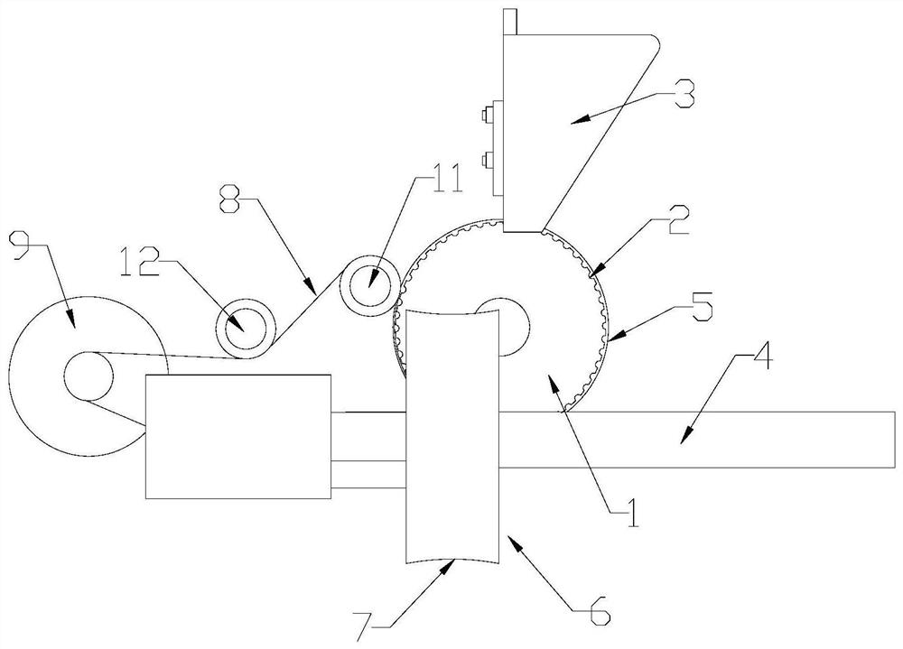
[0024] Such as figure 1 As shown, a resistance welding white shank point angle precision processing device includes a vertically rotating feeding tray 1, the feeding tray 1 is connected to a geared motor, and the rotation of the feeding tray 1 is driven by the geared motor, and the surrounding side wall of the feeding tray 1 A plurality of material storage tanks 2 are arranged at intervals along the circumferential direction, and the material storage tanks 2 are arranged along the axial direction of the feeding tray 1 , and the length of the white handle is greater than the axial length of the material storage tanks 2 . The upper end of the feeding tray 1 is provided with a feeding frame 3, and the feeding frame 3 lowers the white handles into the storage tank 2 one by one. The limit plate 5 of the axis is provided with a vertically rotating grinding wheel 6 on the other side. The axis of the grinding wheel 6 is perpendicular to the axis of the feeding tray 1 , and the axis of...
Embodiment 2
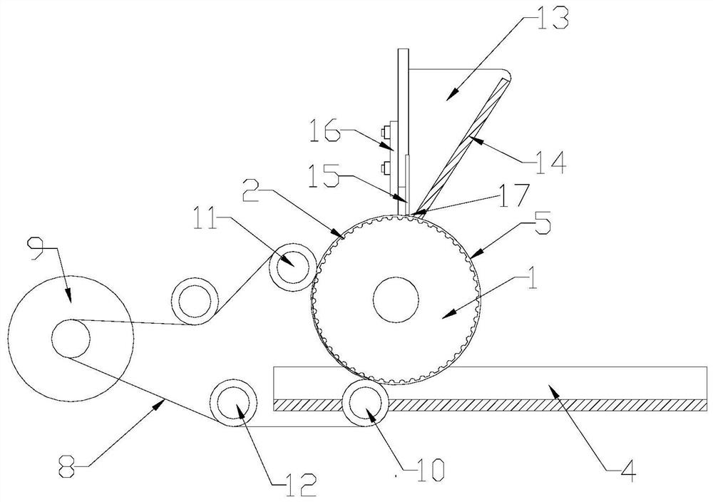
[0029] This embodiment is basically the same as Embodiment 1, the difference is: as figure 2 As shown, the transmission mechanism includes a transmission belt 8 located between the feeding frame 3 and the receiving frame 4 , and the transmission belt 8 rotates along the outer wall of the feeding tray 1 .
[0030] Transmission mechanism also comprises driving motor 9, first positioning roller 10 and second positioning roller 11, and driving motor 9 is a rotary motor, and first positioning roller 10 is positioned at the lower end of feeding tray 1, and the second orientation roller is positioned at feeding tray 1 near the upper end. position, the driving motor 9 is located on the side of the first positioning roller 10 away from the feeding tray 1, one end of the transmission belt 8 is set on the output end of the driving motor 9, and the other end is set on the first positioning roller 10 and the second positioning roller 11, A tension roller 12 is arranged between the first p...
Embodiment 3
[0033] This embodiment is basically the same as embodiment one or two, the difference is: as figure 2 As shown, the loading frame 3 includes a vertical trapezoidal frame 13, one side of the trapezoidal frame 13 is a slope 14 inclined downward, and the other side is vertically provided with a height-adjustable elastic piece 15, the other side of the trapezoidal frame 13 The side is provided with a positioning plate 16, and the positioning plate 16 is provided with a vertical strip-shaped hole, and the upper end of the elastic sheet 15 is fixedly connected with the strip-shaped hole by bolts. Between the elastic sheet 15 and the lower end of the inclined plane 14 is a discharge port 17, and the discharge port 17 only allows the white handles to pass through one by one. The radial distance between the bottom of the storage tank 2 and the discharge port 17 of the loading frame 3 only accommodates one handle; Smaller than the diameter of the white stalk. This structure is adopte...
PUM
 Abstract
Description
Claims
Application Information
 - R&D
- Intellectual Property
- Life Sciences
- Materials
- Tech Scout
- Unparalleled Data Quality
- Higher Quality Content
- 60% Fewer Hallucinations
Browse by: Latest US Patents, China's latest patents, Technical Efficacy Thesaurus, Application Domain, Technology Topic, Popular Technical Reports.
© 2025 PatSnap. All rights reserved.Legal|Privacy policy|Modern Slavery Act Transparency Statement|Sitemap|About US| Contact US: help@patsnap.com


