
Dampening mechanism for offset printing equipment, and printing machine

An equipment and offset printing technology, applied in printing presses, rotary printing presses, lithographic rotary printing presses, etc., can solve the problem of poor contact between the water roller and the plate cylinder, poor water effect of the water roller, and no consideration of the influence of the fountain solution. and other problems, to ensure the effect of water retention, increase efficiency and effect, and avoid freezing

Pending Publication Date: 2020-11-06
刘桂花
View PDF1 Cites 1 Cited by
  • Summary
  • Abstract
  • Description
  • Claims
  • Application Information

AI Technical Summary

Problems solved by technology

[0006] 1. In this scheme, the water impingement roller and the water roller are directly offset. The water impingement effect of the water impregnation roller on the plate cylinder is poor. At the same time, the position of the water roller is adjusted to change the pressure between it and the water roller to control the thickness of the water film, which is easy The contact effect between the water roller and the plate cylinder is poor, which affects the water effect
[0007] 2. This solution does not consider the impact of the environment on the dampening solution, and in some environments it is easy to reduce the dampening effect

Method used


Image

  • Dampening mechanism for offset printing equipment, and printing machine
  • Dampening mechanism for offset printing equipment, and printing machine
  • Dampening mechanism for offset printing equipment, and printing machine

Examples


Embodiment Construction

[0036] The technical solutions of the present invention will be further described below in conjunction with the accompanying drawings and through specific implementation methods.

[0037] Wherein, the accompanying drawings are only for illustrative purposes, showing only schematic diagrams, rather than physical drawings, and should not be construed as limitations on this patent; in order to better illustrate the embodiments of the present invention, some parts of the accompanying drawings will be omitted, Enlarged or reduced, does not represent actual product size.

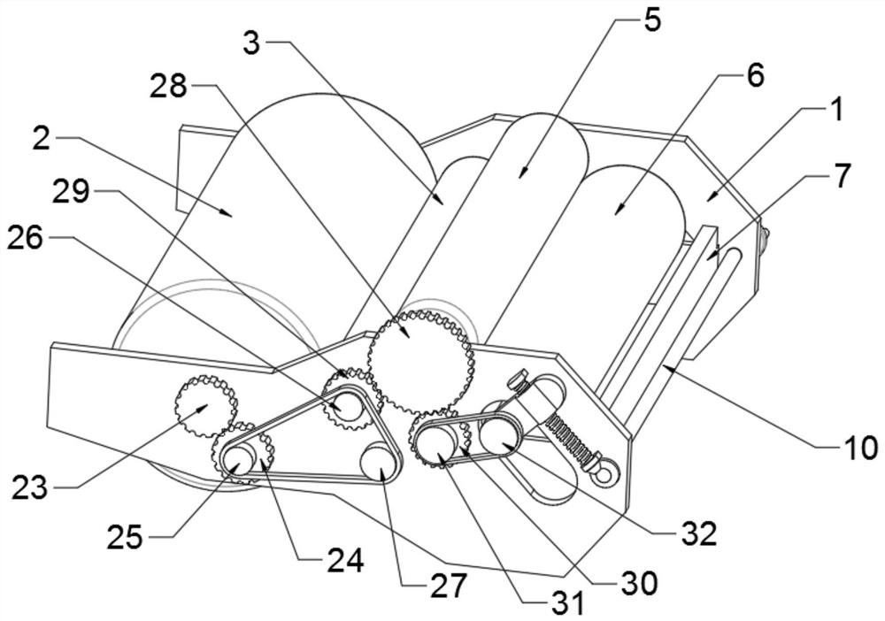
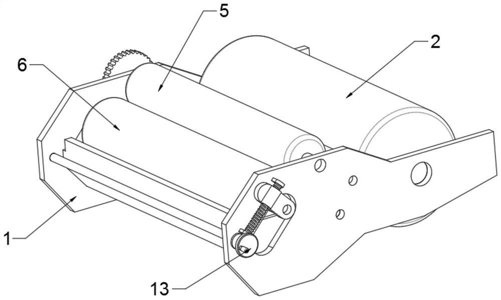
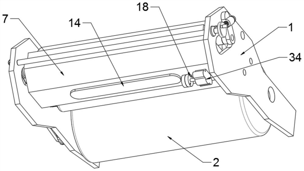
[0038] refer to figure 1 , figure 2 , image 3 and Figure 4 The water landing mechanism of an offset printing equipment shown includes a part of the installation frame body 1, and the plate cylinder 2, the water application roller 3, the water uniform roller 4, the metering roller 5 and the water groove roller 6 are arranged horizontally between the installation frame bodies 1, It can be disassembled and can b...


PUM


Abstract

The invention relates to the field of offset printing equipment, in particular to a dampening mechanism for offset printing equipment, and a printing machine. The dampening mechanism comprises part ofmounting frames; a cylinder, a dampening roller, a water distributing roller, a metering roller and a water tank roller are arranged between the mounting frames in a horizontal-rotation mode; the cylinder abuts against the dampening roller, the water distributing roller is arranged on the lower side of the dampening roller and abuts against the dampening roller, and the metering roller is arranged on the side, away from the cylinder, of the dampening roller and abuts against the dampening roller; the water tank roller is connected with the mounting frames through position control assemblies,a liquid storage tank is fixedly arranged on the lower side of the water tank roller, and the water tank roller extends into the liquid storage tank; and a temperature control assembly is arranged inthe liquid storage tank, the cylinder, the dampening roller and the water distributing roller are connected through a first transmission assembly, and the dampening roller, the metering roller and thewater tank roller are connected through a second transmission assembly. The effect of dampening on the cylinder can be additionally achieved, meanwhile the thickness of a water film can be changed, the purpose of meeting different offset printing demands is achieved, meanwhile the influence on the environment can be avoided, and the offset printing effect is further ensured.

Description

technical field [0001] The invention relates to the field of offset printing equipment, in particular to a watering mechanism and a printing machine of the offset printing equipment. Background technique [0002] Offset printing equipment is a kind of lithographic printing machine. When printing, the printed graphics and texts are first printed from the printing plate to the rubber cylinder, and then transferred to the paper by the rubber cylinder. The elasticity of the rubber cylinder is used to ensure the printing clarity, and the printing effect is better. High, before offset printing, it is often necessary to apply water to the plate cylinder, because the pattern part on the plate cylinder is made of water-repellent material, while the blank part is made of hydrophilic material. Offset sharpness. [0003] However, the thickness of the existing offset printing water film cannot be adjusted. In the case of changing the plate cylinder, etc., the effect of watering is lik...

Claims


Application Information

Patent Timeline
Patent Type & Authority Applications(China)
IPC IPC(8): B41F7/24B41F7/02
CPCB41F7/02B41F7/24
Inventor 刘桂花
Owner 刘桂花
Learn More