A fully enclosed coal conveying system for a thermal power plant

A technology for thermal power plants and coal conveying systems, which is applied in transportation, packaging, loading/unloading, etc., and can solve the problems of direct impact position wear of coal, dust affecting the on-site working environment, and powder spraying of tail guide grooves, etc. Risk of safety accidents, improvement of coal transportation operation environment, and effect of reducing dredging times

Active Publication Date: 2022-02-01
ORDOS JUNZHENG ENERGY CHEM
View PDF6 Cites 0 Cited by
  • Summary
  • Abstract
  • Description
  • Claims
  • Application Information

AI Technical Summary

Problems solved by technology

Caused serious problems such as coal blockage and dust emission of coal handling equipment, and comprehensive transformation of multi-coal types was required
The specific problems are as follows: (1) The coal quality of the received incoming coal has a large water content and a large amount of slime, and the coal is very prone to material hanging and arching in the coal fall. In severe cases, the coal fall will be blocked and the unit will be affected. normal operation
What is even more dangerous is that in order to ensure the normal operation of the unit while loading coal, operators need to enter the coal drop chute for cleaning, increasing the workload of the workers, and there is a risk of personnel falling from a height and coal burying accidents; (2) due to rough During the operation of the crusher and fine crusher, the centrifugal air pressure of the rotor is greater than the dust collection air pressure of the dust collector, resulting in serious powder spraying in the tail guide groove
The raised dust affects the on-site operation environment, and there is a risk of explosion and fire; (3) The unloader of the dust collector is directly connected to the ash hopper, and fine coal powder often enters the bearing through the skeleton oil seal, causing the bearing to lock up and frequent equipment outages , which affects the normal operation of the dust collector; (4) The direct impact position of coal burning is seriously worn, and coal leakage occurs frequently

Method used


Image

  • A fully enclosed coal conveying system for a thermal power plant
  • A fully enclosed coal conveying system for a thermal power plant
  • A fully enclosed coal conveying system for a thermal power plant

Examples


Embodiment

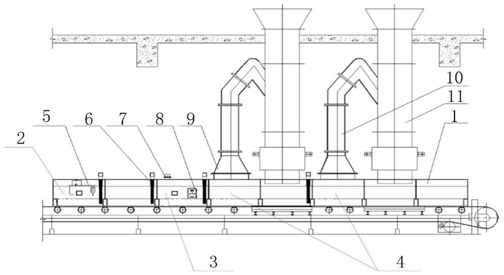
[0025] Such as Figure 1-3 As shown, a fully enclosed coal conveying system for a thermal power plant includes a material guide trough 1, a return pipe 10, and a blanking tube 11. The pipe 11 communicates with the inside of the material guide tank 1, the inside of the material guide tank 1 is provided with a buffer zone 4, an inspection area 3, and a purification area 2, and the intersection of the buffer area 4, inspection area 3, and purification area 2 is provided with a stop Dust device 6, a return pipe 10 is provided directly above the buffer zone 4, and a current collector 9 is provided at the bottom of the return pipe 10, and the current collector 9 is installed on the top of the buffer zone 4, and the inspection area 3 A detection device 7 and a control box 8 are arranged inside, and a spray system 5 is arranged inside the purification area.

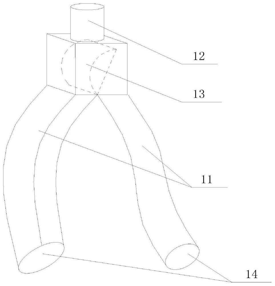
[0026] Specifically, the discharge pipe 11 includes a discharge port 12, a boat-type tee flap 13, and a discharge port 14. The...


PUM


Abstract

The invention discloses a fully enclosed coal conveying system for a thermal power plant, which is characterized in that it includes a material guide trough, a return pipe, and a material drop tube, the material drop tube is arranged at the upper part of one end of the material guide trough, and the material drop The pipe communicates with the inside of the guide trough, and the inside of the guide trough is provided with a buffer zone, an inspection area, and a purification area. A return pipe is provided above, and a collector is provided at the bottom of the return pipe, and the collector is installed on the top of the buffer zone. A detection device and a control box are provided in the inspection area, and a spray nozzle is provided in the purification area. shower system. In actual use, the system can reduce the risk of safety accidents caused by operators cleaning and dredging the coal fall, improve the coal handling environment, and reduce the risk of occupational diseases.

Description

technical field [0001] The invention relates to a material conveying system, in particular to a fully enclosed coal conveying system for a thermal power plant. Background technique [0002] At present, the coal loading system of the power plant has a large daily coal transportation volume and long working hours. Moreover, with the changes in the coal market in recent years, the quality of incoming coal has gradually deteriorated. A series of problems such as burning coal. As a result, problems such as coal blocking and dust emission in coal handling equipment have become prominent, and comprehensive transformation of multiple coal types is required. The specific problems are as follows: (1) The coal quality of the received incoming coal has a large water content and a large amount of slime, and the coal is very prone to material hanging and arching in the coal fall. In severe cases, the coal fall will be blocked and the unit will be affected. normal operation. What is eve...

Claims


Application Information

Patent Timeline
Patent Type & Authority Patents(China)
IPC IPC(8): B65G69/18B65G65/32
CPCB65G69/188B65G69/185B65G65/32
Inventor 张龙乔振宇吴国强裴振全李殿阳王若华窦东官张鑫
Owner ORDOS JUNZHENG ENERGY CHEM
Why Eureka
Try Eureka