Elevator safety brake

A technology of safety brakes and brakes, applied to chemical instruments and methods, hoisting devices, cleaning methods and appliances, etc., can solve problems such as increasing user maintenance frequency, increasing equipment safety hazards, easy loosening of equipment parts, etc., to achieve increased Braking effect, reducing the braking reaction process, and improving the effect of braking time

Active Publication Date: 2020-11-06
苏州东方富力电梯部件有限公司
View PDF20 Cites 1 Cited by
  • Summary
  • Abstract
  • Description
  • Claims
  • Application Information

AI Technical Summary

Problems solved by technology

[0007] The object of the present invention is to provide an elevator safety brake. The structural purpose of the device is to solve the problem of insufficient braking force of the existing brake equipment during use, and the uneven force of the equipment under the impact of a large inertial braking force leads to abnormal vibration of the equipment. The parts of the equipment are easy to loose, which increases the potential safety hazard of the equipment and increases the frequency of user maintenance. By adding a secondary brake mechanism to the device, the brake arm is cleverly used to brake when the brake is closed and the brake shoe brake is encircling the brake disc. , the compression of the secondary brake mechanism forces it to bend upwards and arch to contact the annular bottom surface of the brake disc to assist it in braking, so that the braking inertia is evenly distributed and the braking effect is increased. When the brake disc needs to be repaired, install the elastic blade to start the debugging mode, the brake disc rotates slowly and contacts with the elastic blade, scrapes the attached oil on the surface of the brake disc, and improves the braking effect, so as to solve the problems raised in the above background technology

Method used


Image

  • Elevator safety brake
  • Elevator safety brake
  • Elevator safety brake

Examples


Embodiment Construction

[0035] The technical solutions in the embodiments of the present invention will be clearly and completely described below in conjunction with the accompanying drawings in the embodiments of the present invention. Apparently, the described embodiments are only some, not all, embodiments of the present invention. Based on the embodiments of the present invention, all other embodiments obtained by persons of ordinary skill in the art without making creative efforts belong to the protection scope of the present invention.

[0036] see Figure 1 to Figure 7 , the present invention provides a technical solution:

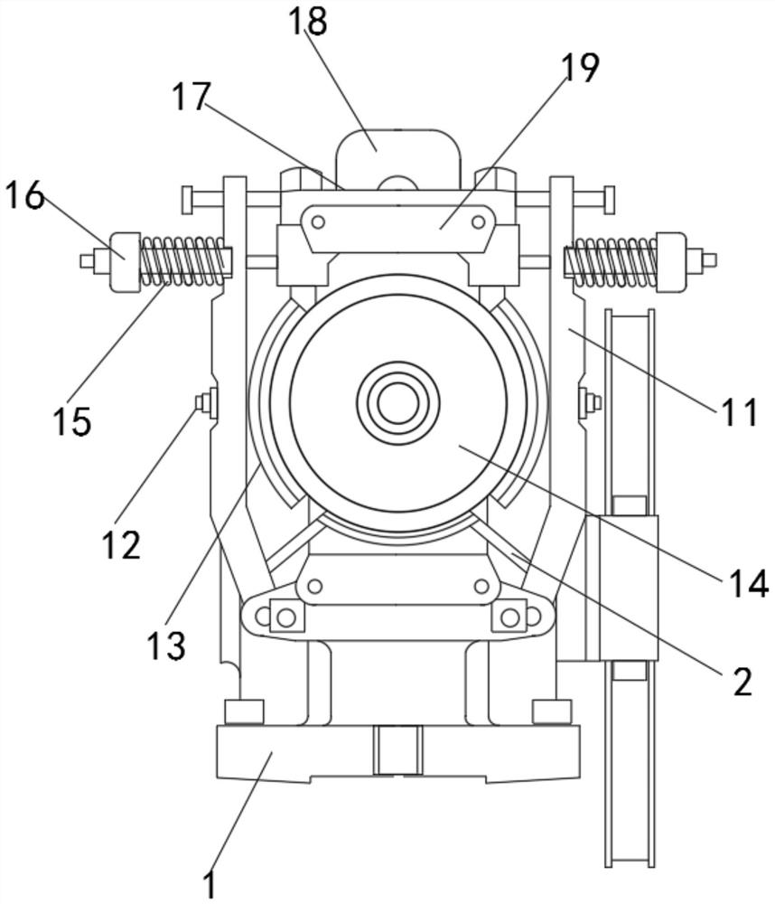
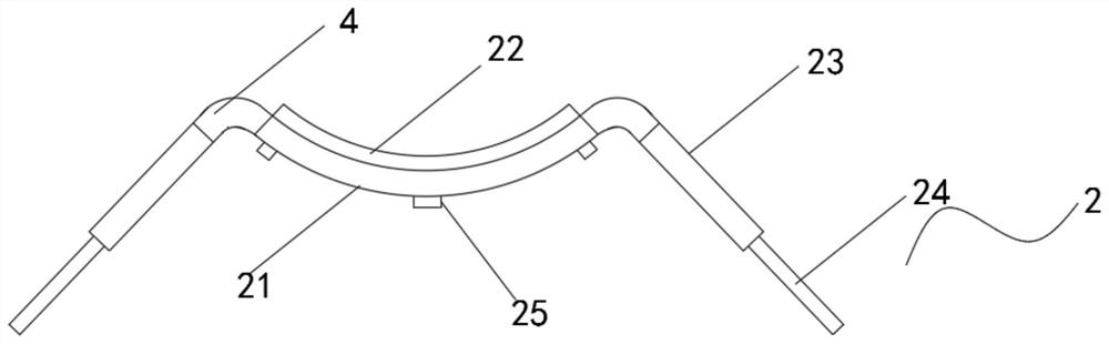
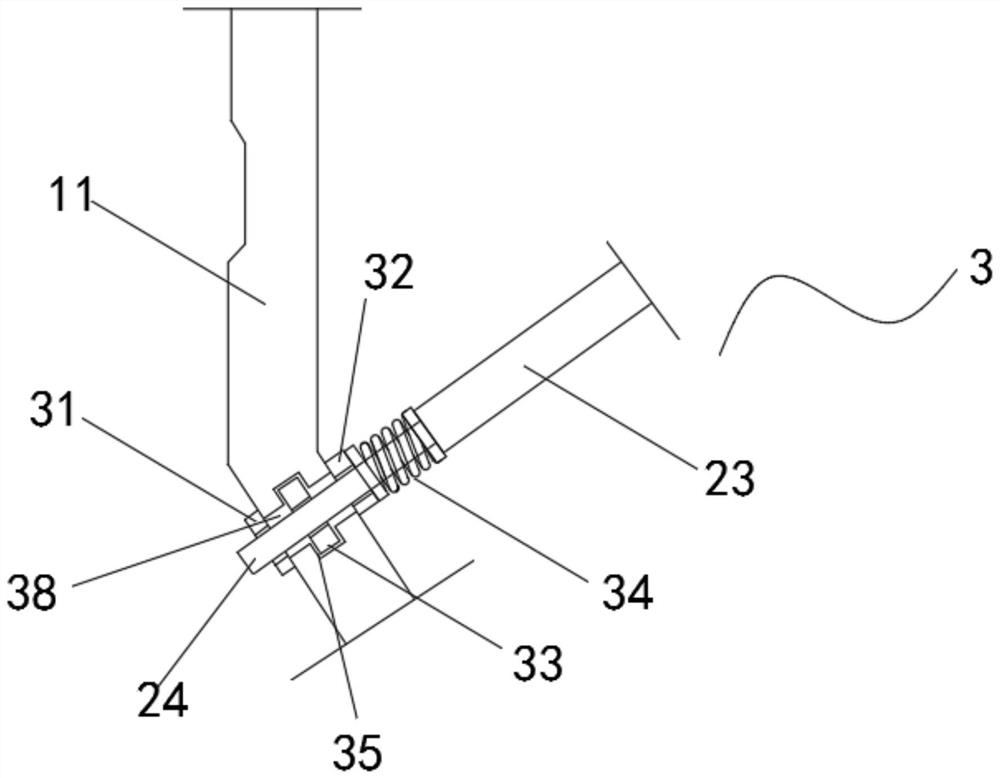
[0037] Such as Figure 1 to Figure 7 As shown, an elevator safety brake includes a base body 1, two brake arms 11, a screw rod 12, two brake shoes 13, a brake disc 14, two spring bodies 15, a spring scale 16, a brake The main body of the brake composed of the rod 17, the plunger 18 and the electromagnet 19, and the bottom ends of the two brake arms 11 are provided with a...


PUM


Abstract

The invention discloses an elevator safety brake. The brake comprises a brake body composed of a base body, two brake arms, a screw, two braking shoe brakes, a brake disc, two spring bodies, a springscale, a brake rod, a plunger and an electromagnet. A secondary brake mechanism is arranged at the bottom ends of the two brake arms, the secondary brake mechanism comprises a secondary brake shoe, abrake pad, primary connecting arms, secondary connecting arms, an elastic bending mechanism and fixing bolts, the brake pad is arranged on the upper end surface of the secondary brake shoe, and the upper end surface of the brake pad is closely attached to the annular side surface of the brake disc. By adding the secondary brake mechanism to the device, when the brake is closed and the brake disc is encircled by the braking shoe brakes for braking, the brake arms are skillfully used, and the secondary brake mechanism is compressed to force the secondary brake mechanism to bend upwards to make contact with the annular bottom end surface of the brake disc to assist the brake disc for braking, so that the braking inertia force is evenly dispersed, and the braking effect is increased.

Description

technical field [0001] The invention relates to the technical field of elevator brakes, in particular to an elevator safety brake. Background technique [0002] The brake is an extremely important safety component of the traction elevator. At present, the brake on the elevator traction machine uses a brake composed of a spring and an electromagnet. At present, most elevators use an electromechanical friction type normally closed brake. The so-called normally closed brake is Refers to the brake that brakes when the machine is not working, and the brake is released when the machine is running. When the elevator brakes, it relies on the action of mechanical force to make the brake belt and the brake wheel friction to generate braking torque. When the elevator is running, it relies on electromagnetic force to make The brake is released, so it is also called electromagnetic brake. [0003] The brake is the basic device to ensure the safe operation of the elevator. It has strict ...

Claims


Application Information

Patent Timeline
Patent Type & Authority Applications(China)
IPC IPC(8): B66D5/08B66D5/30B08B1/00
CPCB08B1/005B66D5/08B66D5/30
Inventor 夏鹏宇刘鹏
Owner 苏州东方富力电梯部件有限公司
Why Eureka
Try Eureka