
Eureka
For R&D, Eureka makes reading and utilizing patents & technical documents easy.
Eureka AIR
Designed for self-driven R&D workflows. Generate viable solutions, solve complex R&D challenges, empower your innovation with AI.

Eureka Materials
Designed for material experts only. Revolutionize your material R&D, from search, analyze, to developing new materials.

TechResearch
Generate reliable direction feasibility study reports for your R&D in just a few steps.

TechSeek
Discover and master advanced knowledge NOW. Basics, ideas, possibilities, all at once.

TechMind
As an expert in R&D Theories, TechMind can generates customized viable solutions instantly.

TechRisk
Analyze your overall solution with one click, know your potential R&D risks in advance.

TechMonitor
Get weekly tech updates, stay abreast of the latest tech innovations and key insights.
Gold plating device and gold plating method
A solution tank and water pump technology, applied in the direction of cells, electrolysis process, electrolysis components, etc., can solve the problems of inability to gold plating, insufficient gold plating, etc.
- Summary
- Abstract
- Description
- Claims
- Application Information
AI Technical Summary
Problems solved by technology
Method used
Image

Examples
Embodiment 1
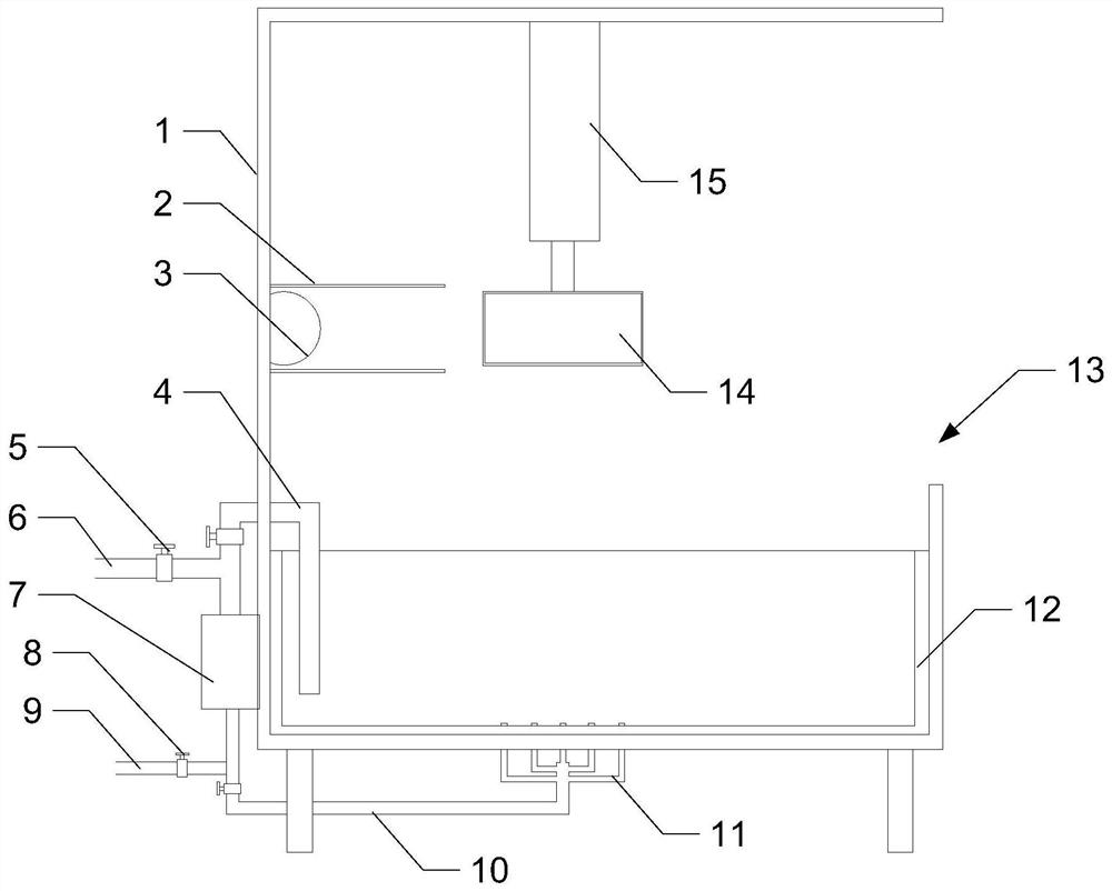
[0033] This embodiment provides a gold plating device, as attached figure 1 shown, including:
[0034] One side of the housing 1 is provided with a feed port 13 .
[0035] The hydraulic machine 15 that is arranged on the casing 1 top.
[0036] The filter box 14 arranged at the output end of the hydraulic machine 15 .
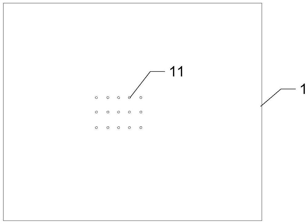
[0037] A solution tank 12 arranged at the bottom of the casing 1 .
[0038] The water pump 7 arranged outside the housing 1, the water inlet of the water pump 7 is connected to the solution tank 12 through a first water inlet pipe 4, and the water outlet of the water pump 7 is connected to the bottom of the solution tank 12 through a first water outlet pipe 10.
[0039] Specifically, the hydraulic press 15 and the solution tank 12 are both arranged on the inner wall of the housing 1 .
[0040] Specifically, the housing 1 has a rectangular structure, of course, it can also be a square structure, an oval structure, etc. according to actual needs.
[0041] Spe...
Embodiment 2
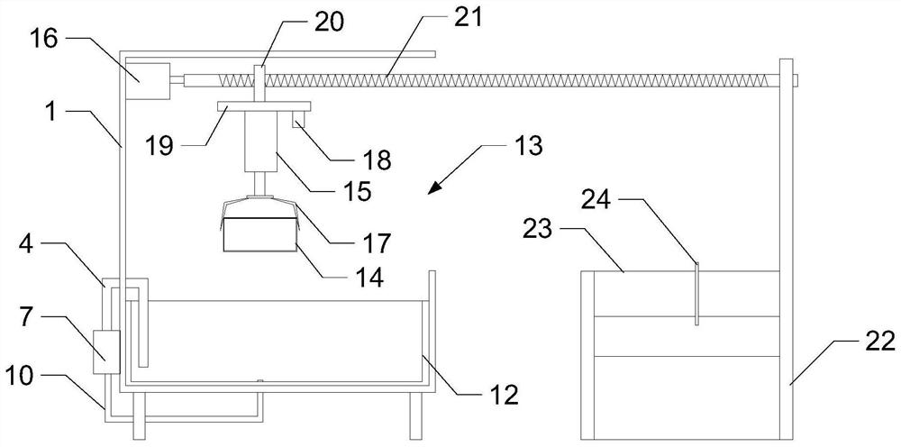
[0071] This embodiment provides another gold plating device, as attached image 3 As shown, it includes: a housing 1 with a feed inlet 13 on one side, a bracket 22 arranged outside the housing 1, a belt conveying mechanism 23 arranged on the bracket 22, and a driving motor arranged on the top of one side of the housing 1 16. The threaded rod 21 connected to the output end of the drive motor 16, the support rod 20 threaded through the threaded rod 21 and threaded with the threaded rod 21, the fixed plate 19 connected with the support rod 20, the fixed plate 19 Camera 18, the hydraulic press 15 arranged on the fixed plate 19, the mechanical claw 17 arranged at the output end of the hydraulic press 15, the filter box 14 grabbed by the mechanical claw 17, the solution tank 12 arranged at the bottom of the housing 1, and the Outer water pump7.
[0072] Wherein, the other end of the threaded rod 21 is rotatably connected to the bracket 22, the water inlet of the water pump 7 is con...
PUM
 Abstract
Description
Claims
Application Information
 - R&D Engineer
- R&D Manager
- IP Professional
- Industry Leading Data Capabilities
- Powerful AI technology
- Patent DNA Extraction
Browse by: Latest US Patents, China's latest patents, Technical Efficacy Thesaurus, Application Domain, Technology Topic, Popular Technical Reports.
© 2024 PatSnap. All rights reserved.Legal|Privacy policy|Modern Slavery Act Transparency Statement|Sitemap|About US| Contact US: help@patsnap.com