
A track-changing anti-twist wire rope braiding machine

A rope braiding machine and track technology, which is applied in the field of track-changing anti-twist wire rope braiding machines, can solve problems such as unstable pay-off tension, small torque, uncontrollable pay-off tension, etc.

Active Publication Date: 2021-02-19
WUXI VOCATIONAL & TECHN COLLEGE
View PDF9 Cites 0 Cited by
  • Summary
  • Abstract
  • Description
  • Claims
  • Application Information

AI Technical Summary

Problems solved by technology

[0002] The existing wire rope braiding machine uses the guide block to move in the guide groove to change the running track of the spindle. During the operation, the guide block hits the guide groove to change the direction, so the mechanical noise is very large during operation;
[0003] Existing knitting machines have uncontrollable pay-off tension during weaving. The reason is that the pay-off tension is achieved by balancing the friction force applied to the drum. When weaving, as the wire on the drum decreases, the diameter becomes smaller and the torque becomes smaller. Small, the pay-off tension is unstable during operation, and it is often necessary to stop and adjust the friction of the drum

Method used


Image

  • A track-changing anti-twist wire rope braiding machine
  • A track-changing anti-twist wire rope braiding machine
  • A track-changing anti-twist wire rope braiding machine

Examples


Embodiment Construction

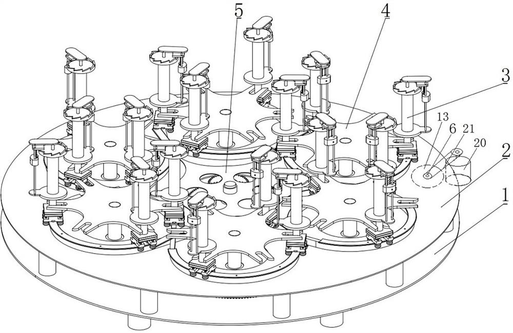
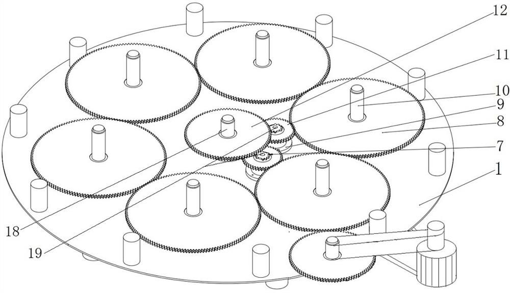
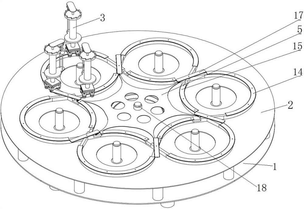
[0047] Refer to attached Figure 1-10 , a track-changing anti-twist wire rope braiding machine is composed of a base part, a gear transmission part, a drum walking track part, a fork part, and a drum winding part 3 (drum assembly):

[0048] The base part has a base 1, and the base 1 is provided with a circular steel plate 1-2. The base 1 is welded by a circular steel plate 1-2 and six cylindrical support columns 1-1. Six groups of base mounting holes 1-4 for the first transmission shaft (main shaft) are evenly distributed on the circular steel plate 1-2 of the machine base, and are used for installing 10 seats of the first transmission shaft (transmission shaft). There are 10 support columns 1-3 distributed on the edge of the circular steel plate for supporting the running track. The middle part of the circular steel plate 1-2 is provided with a central mounting hole 1-5 for mounting the central gear shaft 8 . The lower part of the annular steel plate 1-2 is welded with six...


PUM


Abstract

The invention relates to the field of wire rope braiding for power transmission line pay-off, in particular to a track-changing anti-twist wire rope braiding machine. It is composed of machine base, gear transmission part, roller walking track part, shift fork part, and drum winding part: the machine base part has a machine base, and the outer peripheral part of the circular steel plate of the machine base is evenly distributed with the first transmission shaft, which is installed in the center. A group of central gear shafts, two sets of second transmission shafts distributed in the middle; the gear transmission part includes a large gear, a small gear, an incomplete gear, a central gear, a first transmission shaft, a second transmission shaft, a central gear shaft and a transmission The motor; the roller walking track part is composed of a track installation base, a fixed track, a movable track and a movable track fork; the fork part has a fork, and the fork is installed at the end of the first transmission shaft evenly distributed on the frame; the drum is wound The part includes bogie mechanism, support seat, roller and brake tensioning mechanism; the roller is installed on the upper part of the bogie mechanism, and the roller is equipped with a brake tensioning mechanism.

Description

technical field [0001] The invention relates to the field of traction wire rope weaving for tension payoff of electric power transmission lines, in particular to a track-changing type anti-twist wire rope weaving machine. Background technique [0002] The existing wire rope braiding machine uses the guide block to move in the guide groove to change the running track of the spindle. During the operation, the guide block hits the guide groove to change the direction, so the mechanical noise is very large during operation; [0003] Existing knitting machines have uncontrollable pay-off tension during weaving. The reason is that the pay-off tension is achieved by balancing the friction force applied to the drum. When weaving, as the wire on the drum decreases, the diameter becomes smaller and the torque becomes smaller. Small, the pay-off tension is unstable during operation, and it is often necessary to stop the machine to adjust the friction of the drum. Contents of the inve...

Claims


Application Information

Patent Timeline
Patent Type & Authority Patents(China)
IPC IPC(8): D07B3/00D07B7/02
CPCD07B3/00D07B7/02D07B2207/409
Inventor 王骏马俊峰唐立平芦敏
Owner WUXI VOCATIONAL & TECHN COLLEGE
Learn More