
Pipe network pressure-superposed water supply equipment

A technology of stacking water supply and equipment, applied in water supply devices, lighting and heating equipment, water heaters, etc., can solve problems such as intermittent water intake and filtration, inability to achieve automatic steady flow control, and no ability to automatically heat and heat up cold water. , to achieve the effect of reliable connection, convenient detection and maintenance, and low cost

Inactive Publication Date: 2020-11-06
贺俊威
View PDF9 Cites 2 Cited by
  • Summary
  • Abstract
  • Description
  • Claims
  • Application Information

AI Technical Summary

Problems solved by technology

[0004] The purpose of the present invention is to provide a pipe network superimposed water supply equipment to solve the technical problems in the prior art that do not have the ability to automatically heat up cold water and cannot realize automatic steady flow control and intermittent water intake and filtration.

Method used


Image

  • Pipe network pressure-superposed water supply equipment
  • Pipe network pressure-superposed water supply equipment
  • Pipe network pressure-superposed water supply equipment

Examples


Embodiment Construction

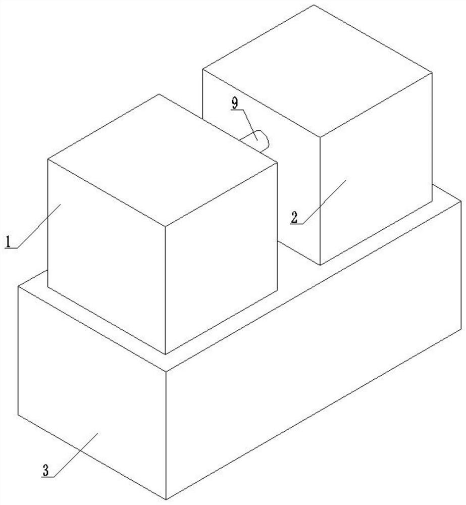
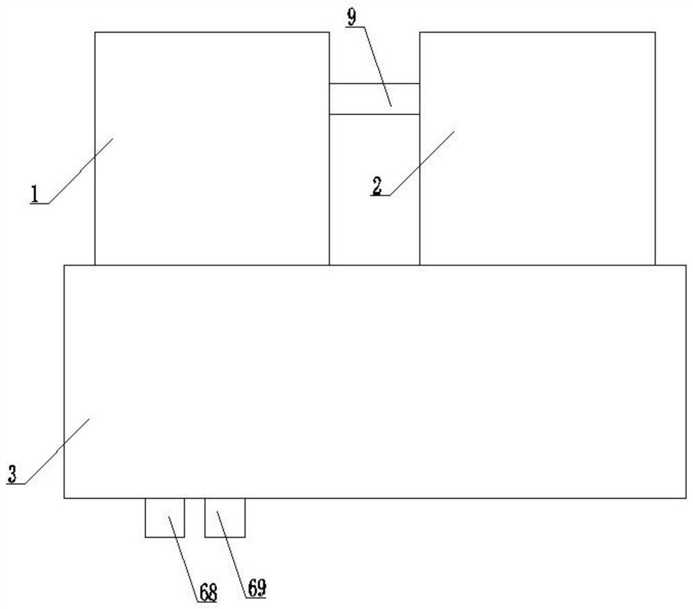
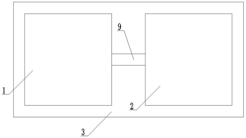
[0028] The present invention is described in detail below in conjunction with accompanying drawing:

[0029] refer to Figure 1 to Figure 9 , a pipe network superimposed water supply equipment provided by the present invention includes a water intake chamber 3, the top of the water intake chamber 3 is sequentially provided with a control room 1 and a water supply room 2 from left to right, and the inside of the control room 1 A water reservoir 5 is provided, the lower side of the water reservoir 5 is provided with an upper water pipe 4, and the right side of the water reservoir 5 is provided with a first conducting pipe 7, and the first conducting pipe 7 is provided on the right side of the water reservoir 5. The right end of the pipe 7 communicates with the left end of the second conduction pipe 9 through the one-way valve 8, the right end of the second conduction pipe 9 extends into the interior of the water supply chamber 2, and the interior right side of the control chambe...


PUM


Abstract

The invention provides pipe network pressure-superposed water supply equipment. The equipment comprises a water taking chamber, wherein a temperature control chamber and a water supply chamber are sequentially arranged at the top of the water taking chamber from left to right, a water storage device is arranged inside the temperature control chamber, and a water feeding pipe is arranged on the lower side face of the water storage device; a first communicating pipe is arranged on the right side face of the water storage device, the right end of the first communicating pipe communicates with theleft end of a second communicating pipe through a one-way valve, and the right end of the second communicating pipe extends into the water supply chamber; a first electric cylinder bottom plate is fixed to the right side face of the interior of the temperature control chamber through a first series of bolt sets, and the left end of the first electric cylinder bottom plate is fixedly connected with the right end of a first electric cylinder; and a first action rod is arranged at the power output end at the left side of the first electric cylinder, and a heater is arranged at the left end of the first action rod. By means of the technical scheme, the technical problems that in the prior art, the automatic heating capacity for cold water is not achieved, automatic flow stabilizing control cannot be achieved, and intermittent water taking and filtering cannot be achieved are effectively solved, and application and popularization are facilitated.

Description

technical field [0001] The invention relates to the technical field of water supply equipment, in particular, to a water supply equipment with overlapping pipe networks. Background technique [0002] Water supply equipment is an automatic start-stop water supply device that outputs a certain flow rate and lift per unit time. It is divided into four categories according to its use: fire protection, life, production, and sewage treatment. In recent years, with the rapid development of the economy, high-rise buildings have sprung up all over the place, standing in front of people one by one. However, since the pressure of the municipal pipe network can only reach about 0.2MPa, the water pressure and water quality of high-rise users have been plagued by the designers of the water supply company. With the development of technology, the appearance of pipe network overlapping water supply equipment has made The above problems are easily solved. [0003] Pipe network superimposed ...

Claims


Application Information

Patent Timeline
Patent Type & Authority Applications(China)
IPC IPC(8): E03B7/00E03B7/07E03B7/12F24H1/18F24H9/18F24H9/20
CPCE03B7/00E03B7/07E03B7/12F24H1/185F24H9/1818F24H9/2021
Inventor 贺俊威
Owner 贺俊威
Learn More