Multifunctional electric heater

An electric heater and multi-functional technology, applied in the field of multi-functional electric heaters, can solve the problems of complex structure of electric heaters, and achieve the effects of convenient installation and subsequent maintenance, simple overall structure and ingenious conception.

Inactive Publication Date: 2020-11-06
冯杰慧
View PDF20 Cites 1 Cited by
  • Summary
  • Abstract
  • Description
  • Claims
  • Application Information

AI Technical Summary

Problems solved by technology

[0005] In order to overcome the problem that the structure of the existing electric heater with both humidification and heating functions is relatively complicated, the present invention provides an electric heater, the specific technical solution of which is as follows:

Method used


Image

  • Multifunctional electric heater
  • Multifunctional electric heater
  • Multifunctional electric heater

Examples


Embodiment 1

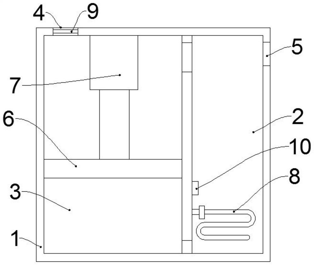
[0034] Such as figure 1 As shown, a multifunctional electric heater includes a first casing 1 and a fan 9, the first casing 1 is provided with a first chamber 2 and a second chamber 3, and the side wall of the first chamber 2 The bottom communicates with the bottom of the side wall of the second chamber 3, the top of the side wall of the first chamber 2 communicates with the top of the side wall of the second chamber 3, and the second chamber 3 is far away from the first chamber. The top of the side wall of the chamber 2 is provided with an air inlet 4, and the top of the side wall of the first chamber 2 away from the second chamber 3 is provided with an air outlet 5, and the fan 9 is installed in the air inlet 4 .

[0035] Another example figure 1 As shown, the multifunctional electric heater also includes a piston 6, a telescopic assembly 7 and a heating assembly 8, the piston 6 is in sliding and sealing connection with the side wall of the second chamber 3, and the telesc...

Embodiment 2

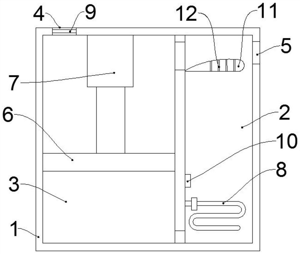
[0048] Such as figure 1 As shown, a multifunctional electric heater includes a first casing 1 and a fan 9, the first casing 1 is provided with a first chamber 2 and a second chamber 3, and the side wall of the first chamber 2 The bottom communicates with the bottom of the side wall of the second chamber 3, the top of the side wall of the first chamber 2 communicates with the top of the side wall of the second chamber 3, and the second chamber 3 is far away from the first chamber. The top of the side wall of the chamber 2 is provided with an air inlet 4, and the top of the side wall of the first chamber 2 away from the second chamber 3 is provided with an air outlet 5, and the fan 9 is installed in the air inlet 4 .

[0049] Another example figure 1 As shown, the multifunctional electric heater also includes a piston 6, a telescopic assembly 7 and a heating assembly 8, the piston 6 is in sliding and sealing connection with the side wall of the second chamber 3, and the telesc...

Embodiment 3

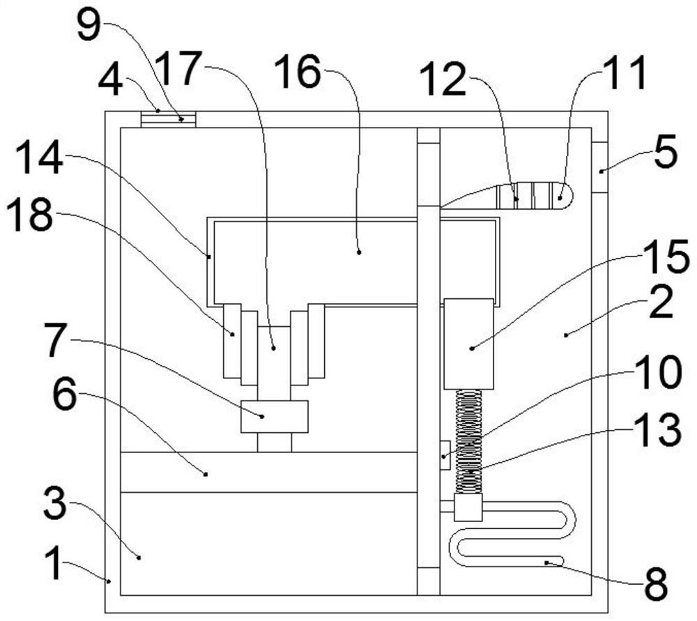
[0063] Such as figure 1 As shown, a multifunctional electric heater includes a first casing 1 and a fan 9, the first casing 1 is provided with a first chamber 2 and a second chamber 3, and the side wall of the first chamber 2 The bottom communicates with the bottom of the side wall of the second chamber 3, the top of the side wall of the first chamber 2 communicates with the top of the side wall of the second chamber 3, and the second chamber 3 is far away from the first chamber. The top of the side wall of the chamber 2 is provided with an air inlet 4, and the top of the side wall of the first chamber 2 away from the second chamber 3 is provided with an air outlet 5, and the fan 9 is installed in the air inlet 4 .

[0064] Another example figure 1 As shown, the multifunctional electric heater also includes a piston 6, a telescopic assembly 7 and a heating assembly 8, the piston 6 is in sliding and sealing connection with the side wall of the second chamber 3, and the telesc...


PUM


Abstract

The invention provides a multifunctional electric heater. The multifunctional electric heater comprises a first shell, a fan, a piston, a telescopic component and a heating component; a first cavity and a second cavity are arranged inside the first shell; the bottom of the side wall of the first cavity communicates with the bottom of the side wall of the second cavity; the top of the side wall ofthe first cavity communicates with the top of the side wall of the second cavity; the top of the side wall of the second cavity away from the first cavity is provided with an air inlet; the top of theside wall of the first cavity away from the second cavity is provided with an air outlet; the fan is installed in the air inlet; the piston is in sliding and sealed connection with the side wall of the second cavity; the telescopic component is installed in the second cavity; one end of the telescopic component is fixedly connected with the piston; the telescopic component is used for driving thepiston to slide along the side wall of the second cavity; and the heating component is installed in the first cavity. The multifunctional electric heater provided by the invention has the functions of air humidification and air heating, and can humidify or heat indoor air as required.

Description

technical field [0001] The invention relates to the field of electric heaters, in particular to a multifunctional electric heater. Background technique [0002] Electric heater is a device that converts electrical energy into heat energy. Compared with traditional fuel heating, it has the advantages of cleanliness, no pollution, high thermal efficiency, and convenient temperature control and adjustment. It is currently widely used in daily life. [0003] After a large number of searches, some typical existing technologies were found. For example, the patent application number 201810006219.0 discloses a heater with purification, disinfection, and humidification functions, including a shell, and a cross-flow fan is arranged in the shell sequentially from bottom to top , a purification and disinfection chamber, an upper equalizing heat insulation board, and an electric heating device. A vertical channel is formed between the front side of the purification and disinfection chamb...

Claims


Application Information

Patent Timeline
Patent Type & Authority Applications(China)
IPC IPC(8): F24D13/02F24D19/06F24F6/10F24F13/20
CPCF24D13/02F24D19/06F24F6/10F24F13/20
Inventor 冯杰慧
Owner 冯杰慧
Why Eureka
Try Eureka