Optical cable cross-connecting box

An optical cable junction box and optical cable technology, which is applied in optics, light guides, optical components, etc., can solve the problems of the failure of automatic fusion splicing of trunk optical cables and the lack of wiring optical cables, so as to reduce labor costs, reliable connections, and low implementation costs. Effect

Inactive Publication Date: 2020-11-06
吴娟
View PDF0 Cites 0 Cited by
  • Summary
  • Abstract
  • Description
  • Claims
  • Application Information

AI Technical Summary

Problems solved by technology

[0004] The purpose of the present invention is to provide an optical cable transfer box to solve the technical problems in the prior art that do not have the ability to automatically weld the distribution optical cable and the main optical cable, and cannot realize the quality inspection of the optical cable to be tested, and the cooling of the device.

Method used


Image

  • Optical cable cross-connecting box
  • Optical cable cross-connecting box
  • Optical cable cross-connecting box

Examples


Embodiment Construction

[0029] The present invention is described in detail below in conjunction with accompanying drawing:

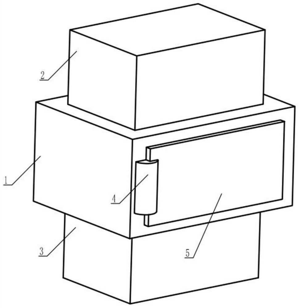
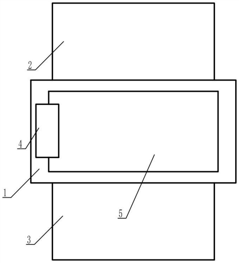
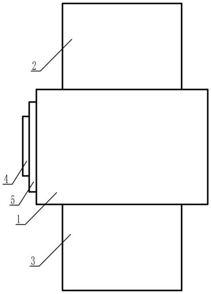
[0030] refer to Figure 1 to Figure 9 , a kind of optical cable transfer box provided by the present invention includes a fusion splice box 1, the top of the fusion splice box 1 is provided with an inspection box 2, the bottom of the fusion splice box 1 is provided with a cooling box 3, and the fusion splice box 1 The front surface of the welding box 1 is provided with a turning half shaft 4, the right side of the turning half shaft 4 is connected to the left side of the revolving door 5, and the inner lower surface of the welding box 1 is fixed with a first motor bottom plate 6, the said The top of the first motor bottom plate 6 is provided with a first motor 7, and the top power output end of the first motor 7 is provided with a power shaft 8, and the top of the power shaft 8 is connected to the shaft coupling 9 and the rotating shaft 10. The bottom end is fixedly connected...


PUM


Abstract

The invention provides an optical cable cross-connecting box, which comprises a welding box, wherein an inspection box is arranged at the top of the welding box, a cooling box is arranged at the bottom of the welding box, a rotating half shaft is arranged on the front surface of the welding box, the right side of the rotating half shaft is connected with the left side of a rotating door, a first motor bottom plate is fixed to the lower surface of the interior of the welding box, a first motor is arranged at the top of the first motor bottom plate, a power shaft is arranged at the top power output end of the first motor, the top of the power shaft is fixedly connected with the bottom end of a rotating shaft through a coupler, a driving friction cylinder is arranged at the top end of the rotating shaft, the rear end of the periphery of the driving friction cylinder is in contact fit with the first friction strip, and the left end of the periphery of the driving friction cylinder is in contact fit with a driven friction cylinder. According to the technical scheme disclosed by the invention, the technical problems that in the prior art, the automatic welding capacity of the distribution optical cable and the main optical cable is not achieved, and quality inspection, cooling and the like of the to-be-detected optical cable cannot be achieved are effectively solved, and popularization and application are facilitated.

Description

technical field [0001] The present invention relates to the technical field of communication network equipment, in particular, to an optical cable transfer box. Background technique [0002] Optical cables are manufactured to meet optical, mechanical or environmental performance specifications. It is a communication cable assembly that uses one or more optical fibers placed in a sheath as a transmission medium and can be used individually or in groups. Optical cables The transfer box is mainly used for the interface equipment at the junction of the backbone optical cable and the distribution optical cable in the optical cable access network. The optical cable transfer box is a connecting device installed outdoors. The most fundamental requirement for it is to be able to withstand drastic changes in climate and harsh working environments. It should have the characteristics of waterproof condensation, waterproof and dustproof, insect pest and rodent proof, and strong resistan...

Claims


Application Information

Patent Timeline
IPC IPC(8): G02B6/44G02B6/255G01M11/00G01N27/00
CPCG01M11/30G01N27/00G02B6/2551G02B6/2553G02B6/443G02B6/4436G02B6/4446
Inventor 吴娟
Owner 吴娟
Why Eureka
Try Eureka