Special-shaped compression-resistant optical cable
A fiber optic cable and special-shaped technology, applied in the field of cables, can solve problems such as unfavorable production, weak lateral pressure resistance, complex structure, etc., and achieve the effect of simple structure
- Summary
- Abstract
- Description
- Claims
- Application Information
AI Technical Summary
Problems solved by technology
Method used
Image

Examples
Embodiment 1
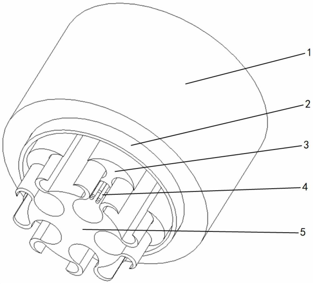
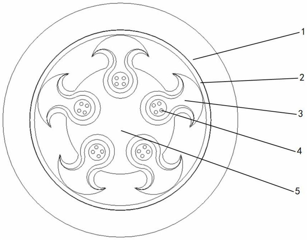
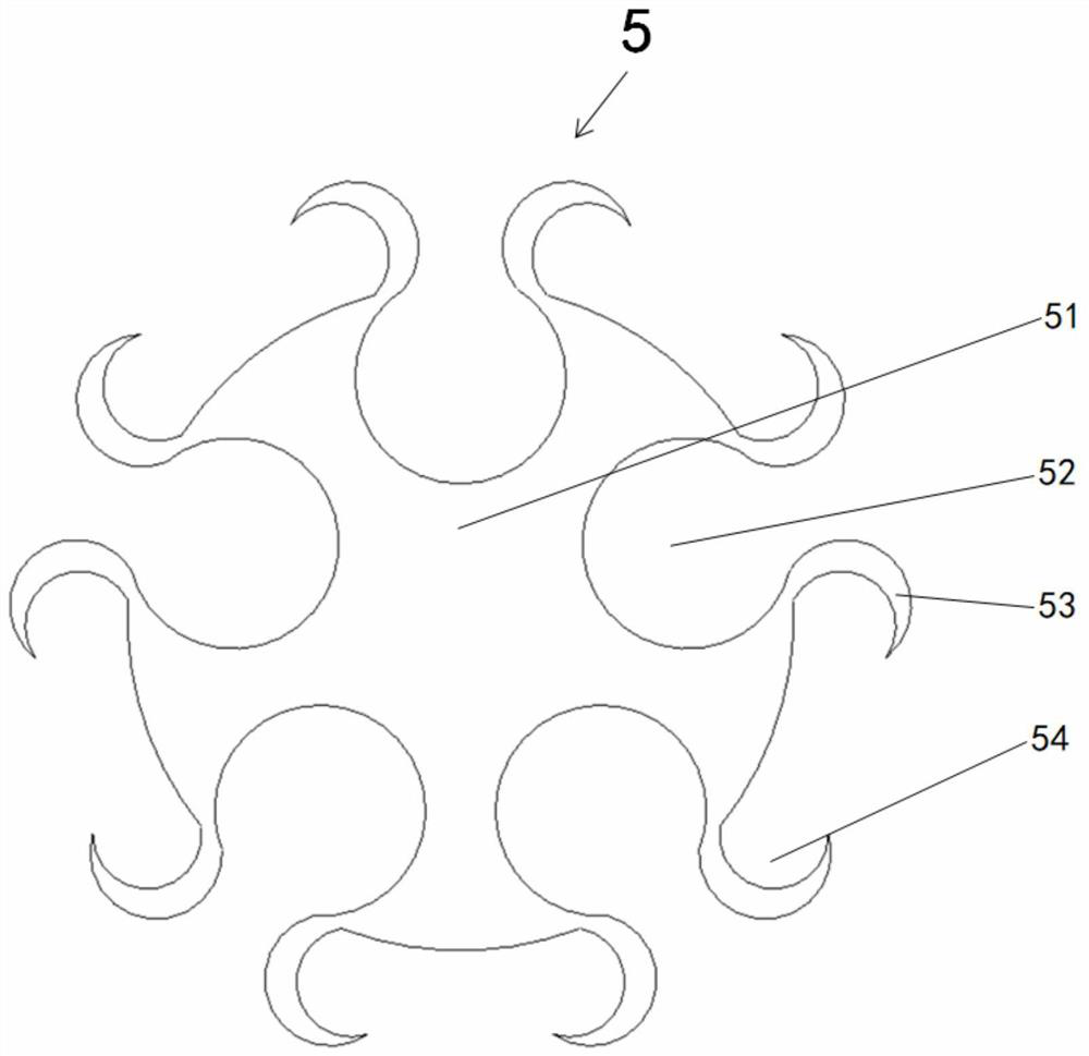
[0030] please see figure 1 , figure 2 , image 3 and Figure 4 , a special-shaped pressure-resistant optical cable, which is composed of an outer sheath 1, a tape layer 2, a plurality of loose tubes 3 and a skeleton 5, the tape layer 2 is located outside the skeleton 5, and the outer sheath 1 is located outside the tape layer 2, It is characterized in that the frame 5 is composed of a frame body 51, and a plurality of loose tube cavities 52 are arranged on the frame body 51, and a pair of arc-shaped compression parts 53 are provided at both ends of the opening of each loose tube cavity 52 , a groove 54 is formed inside each compression member 53, and the loose tube 3 is composed of a loose tube main body 34, a rib 33 and an anchoring part 31. 33 above, the two sides of the hanging member 31 and the rib 33 form two arc-shaped hanging grooves 32, and the inside of the loose tube main body 34 forms an optical communication unit cavity 35, and the optical communication unit ca...
Embodiment 2
[0032] please see image 3 , Figure 4 , Figure 5 and Figure 6 , a special-shaped pressure-resistant optical cable, which is composed of an outer sheath 1, a tape layer 2, a plurality of loose tubes 3 and a skeleton 5, the tape layer 2 is located outside the skeleton 5, and the outer sheath 1 is located outside the tape layer 2, It is characterized in that the frame 5 is composed of a frame body 51, and a plurality of loose tube cavities 52 are arranged on the frame body 51, and a pair of arc-shaped compression parts 53 are provided at both ends of the opening of each loose tube cavity 52 , a groove 54 is formed inside each compression member 53, and the loose tube 3 is composed of a loose tube main body 34, a rib 33 and an anchoring part 31. 33 above, the two sides of the hanging member 31 and the rib 33 form two arc-shaped hanging grooves 32, and the inside of the loose tube main body 34 forms an optical communication unit cavity 35, and the optical communication unit c...
Embodiment 3
[0036] please see image 3 , Figure 4 , Figure 7 and Figure 8, a special-shaped pressure-resistant optical cable, which is composed of an outer sheath 1, a tape layer 2, a plurality of loose tubes 3 and a skeleton 5, the tape layer 2 is located outside the skeleton 5, and the outer sheath 1 is located outside the tape layer 2, It is characterized in that the frame 5 is composed of a frame body 51, and a plurality of loose tube cavities 52 are arranged on the frame body 51, and a pair of arc-shaped compression parts 53 are provided at both ends of the opening of each loose tube cavity 52 , a groove 54 is formed inside each compression member 53, and the loose tube 3 is composed of a loose tube main body 34, a rib 33 and an anchoring part 31. 33 above, the two sides of the hanging member 31 and the rib 33 form two arc-shaped hanging grooves 32, and the inside of the loose tube main body 34 forms an optical communication unit cavity 35, and the optical communication unit ca...
PUM
 Abstract
Description
Claims
Application Information
 - R&D
- Intellectual Property
- Life Sciences
- Materials
- Tech Scout
- Unparalleled Data Quality
- Higher Quality Content
- 60% Fewer Hallucinations
Browse by: Latest US Patents, China's latest patents, Technical Efficacy Thesaurus, Application Domain, Technology Topic, Popular Technical Reports.
© 2025 PatSnap. All rights reserved.Legal|Privacy policy|Modern Slavery Act Transparency Statement|Sitemap|About US| Contact US: help@patsnap.com