Single-hand thread tightening and breaking type haemorrhoids loop ligation device for anorectal department
An anorectal and ligation device technology, applied in the field of medical equipment, can solve the problems of narrow space, inconvenient operation, easy breakage of the rubber ring, etc.
- Summary
- Abstract
- Description
- Claims
- Application Information
AI Technical Summary
Problems solved by technology
Method used
Image
Examples
Embodiment 1
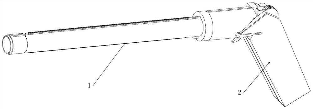
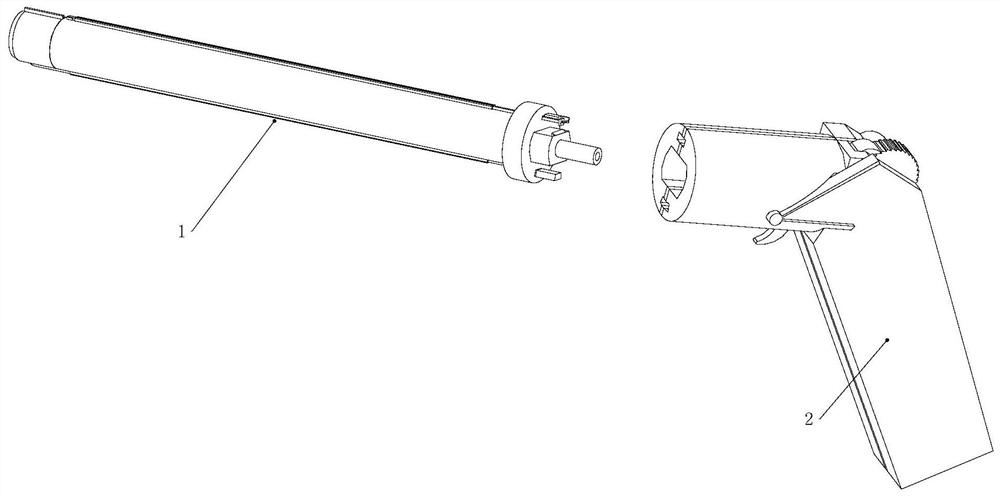
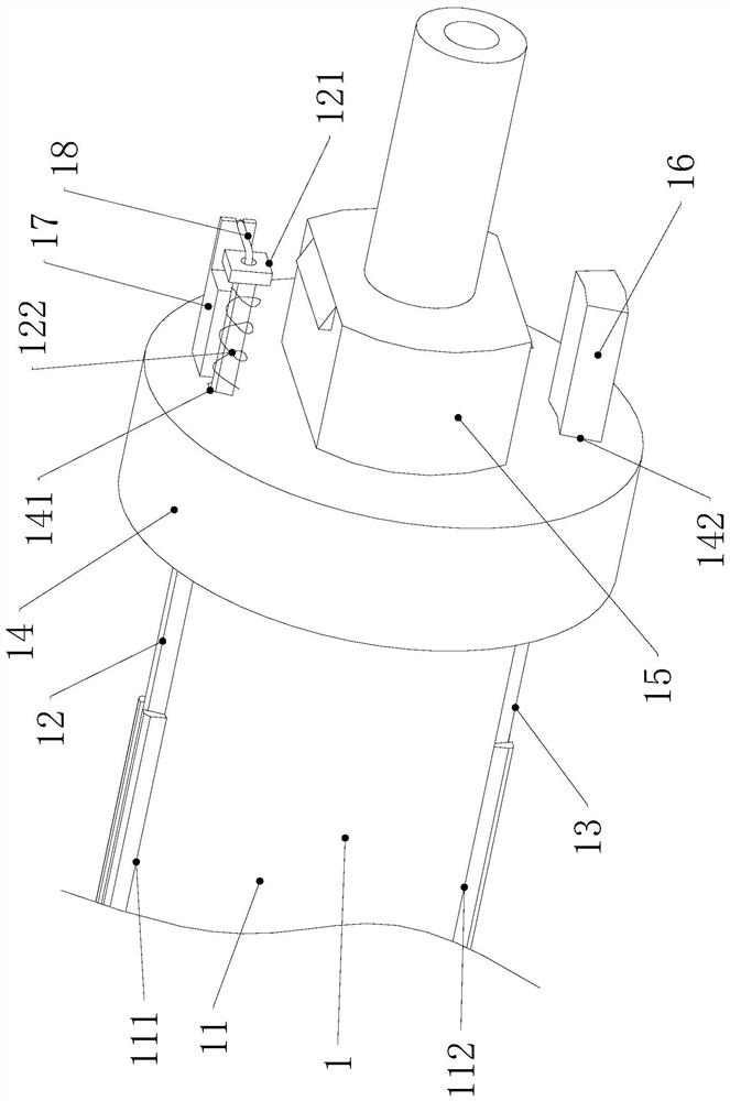
[0046] Embodiment one, refer to Figure 1-7 and Figure 11 , a hemorrhoid ligation device for anorectal department with one-hand tight thread and broken thread, comprising a ligation tube 1 and a gun body 2, and the ligation tube 1 includes a main body 11, a first push rod 12, a second push rod 13, and a positioning ring 14 , buckle 15, ligation line 18, push ring 19; the main body 11 is fixedly connected with the positioning ring 14, and the positioning ring 14 is fixedly connected with the buckle 15; the ligation tube 1 and the gun body 2 are detachably connected through the buckle 15; The surface of the main body 11 is provided with a first slideway 111, the first push rod 12 is located in the first slideway 111 and connected by sliding, the surface of the main body 11 is provided with a second slideway 112, and the second pushrod 13 is located in the second slideway The top of the second push rod 13 is fixedly connected with the push ring 19, and the push ring 19 is locat...
Embodiment 2
[0047] Embodiment two, refer to Figure 8-12 The wire pushing mechanism 22 includes a first paddle 221, a second paddle 222, a third push rod 223 and a first return spring 224; the first paddle 221 and the second paddle 222 are fixedly connected by a rotating shaft, and the The rotating shaft is rotatably connected with the casing 21; the casing 21 is provided with a first limiting groove 2101, a third chute 2102 and a first spring groove 2104, and the outer surface of the casing 21 is provided with an outer limiting groove 2108; the first paddle 221 is located in the first limiting groove 2101 and is rotatably connected; the second paddle 222 is located in the outer limiting groove 2108 and is rotatably connected; the third push rod 223 is located in the third chute 2102 and is slidably connected; the third push rod 223 It is crimped with the second plectrum 222; the end of the check block 161 is located in the third chute 2102, and the third push rod 223 is crimped with the ...
Embodiment 3
[0048] Embodiment three, refer to Figures 13 to 15 , Figures 18-19 and Figure 21 , the wire tightening mechanism 23 includes a pull button 231, a second return spring 232, a pull wire 233, a ratchet winch 234 and a pawl 235; the casing 21 is provided with a pull button chute 2103, and the end of the pad 17 is located in the pull button chute 2103 Inside, the pull button 231 is located in the pull button chute 2103 and is slidably connected, and the hook portion of the pull button 231 is located in the first gap 171 of the pad 17, and the pull button 231 is connected with the ligation line 18; the pull button 231 Be connected with backguy 233, and backguy 233 is connected with ratchet winch 234; Ratchet winch 234 is connected with shell 921 rotation; Pawl (235 and shell (21 are connected by hinge, and hinge position is provided with torsion spring, ratchet 235 and ratchet winch 234 Clamping; the shell 21 is provided with a second spring slot 2105 , and the second spring sl...
PUM
 Abstract
Description
Claims
Application Information
 - R&D
- Intellectual Property
- Life Sciences
- Materials
- Tech Scout
- Unparalleled Data Quality
- Higher Quality Content
- 60% Fewer Hallucinations
Browse by: Latest US Patents, China's latest patents, Technical Efficacy Thesaurus, Application Domain, Technology Topic, Popular Technical Reports.
© 2025 PatSnap. All rights reserved.Legal|Privacy policy|Modern Slavery Act Transparency Statement|Sitemap|About US| Contact US: help@patsnap.com


