Annular joint device for facilitating rust removal by laser cleaning machine

A joint device and cleaning agent technology, which is applied in the field of laser cleaning, can solve difficult problems such as processing, and achieve the effects of improving utilization, saving labor resources, and improving work efficiency

Active Publication Date: 2020-11-10
中国南方电网有限责任公司超高压输电公司柳州局
View PDF22 Cites 0 Cited by
  • Summary
  • Abstract
  • Description
  • Claims
  • Application Information

AI Technical Summary

Problems solved by technology

At present, the laser output by the laser cleaning machine is a wire beam light, which needs to be moved to clean the entire surface of the workpiece. This is easy to handle for regular workpieces, but it is difficult to handle cylindrical towers and irregular workpieces on the grid.

Method used


Image

  • Annular joint device for facilitating rust removal by laser cleaning machine
  • Annular joint device for facilitating rust removal by laser cleaning machine
  • Annular joint device for facilitating rust removal by laser cleaning machine

Examples


Embodiment 1

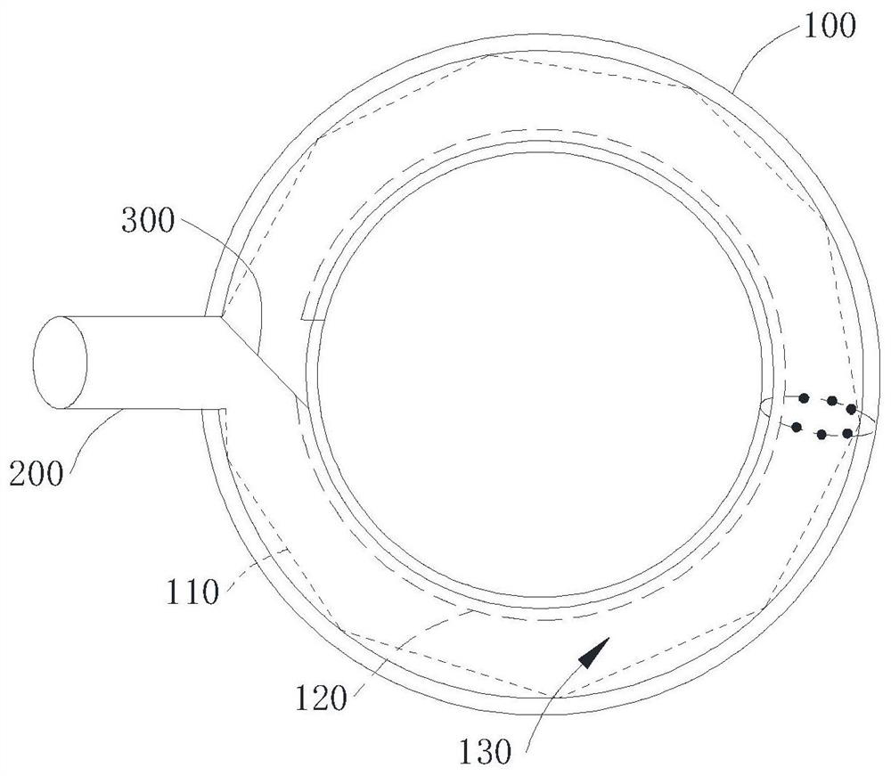
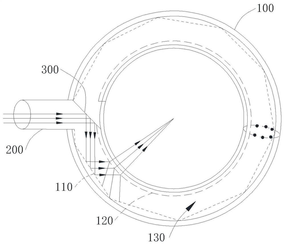
[0032] Please refer to figure 1 with figure 2 , a ring joint device for laser cleaning agent derusting, comprising an outer layer mirror 110, an inner layer mirror 120, a first cylindrical laser input tube 200 and a first total reflection mirror 300 at the beginning, and the outer layer mirror 110 is composed of several total reflection mirrors Formed in a circular arrangement, the inner mirror 120 is formed by a number of half-reflecting mirrors arranged in a ring, the inner mirror 120 is arranged in the area enclosed by the outer mirror 110, and the outer mirror 110 and the inner mirror 120 form a ring reflection Area 130, the outer layer mirror 110 is provided with an opening along the ring direction, the first cylindrical laser input tube 200 communicates with the reflection area at the opening, the first cylindrical laser input tube 200 is configured to deliver the line beam laser, the first initial section The total reflection mirror 300 is disposed in the annular refl...

Embodiment 2

[0046] Please refer to Figure 4 , Figure 4 For this embodiment of the present invention, a laser cleaning agent derusting ring joint device is provided.

[0047] This embodiment provides a laser cleaning agent derusting annular joint device, which is roughly the same as the laser cleaning agent derusting annular joint device of the first embodiment, the difference between the two is that the second cylindrical laser input tube 400 of this embodiment With the second total reflection mirror 500 at the beginning.

[0048] Please refer to Figure 4 , the laser cleaning agent derusting annular joint device is also provided with a second cylindrical laser input tube 400, and the second cylindrical laser input tube 400 is equipped with a second initial total reflection mirror 500, and the second cylindrical laser input tube 400 is connected to the second cylindrical laser input tube 400. A cylindrical laser input tube 200 is arranged side by side and all communicates with the an...


PUM


Abstract

Disclosed is an annular joint device for facilitating rust removal by a laser cleaning machine. The annular joint device comprises an outer-layer mirror, an inner-layer mirror, a first cylindrical laser input pipe and a first initial-section total reflection mirror, wherein the outer-layer mirror is formed through annular distribution of a plurality of total reflection mirrors, the inner-layer mirror is formed by through annular distribution of a plurality of half reflection mirrors, and the inner-layer mirror is arranged in an area defined by the outer-layer mirror. The outer-layer mirror andthe inner-layer mirror define an annular reflection area, the outer-layer mirror is provided with an opening in the circumferential direction, the first cylindrical laser input pipe communicates withthe reflection area at the opening, and is configured to convey wire harness laser, the first initial-section total reflection mirror is arranged in the annular reflection area, and the reflection surface of the first initial-section total reflection mirror is obliquely arranged at the opening and is arranged in the direction of the central line of the annular reflection area. The annular joint device can convert input wire harness laser into ring-shaped laser, is suitable for surface purification treatment of cylinders and irregular workpieces, is convenient to implement, and can save energy, and improve the cleaning efficiency, thereby achieving quick treatment and reducing energy consumption.

Description

technical field [0001] The invention relates to the technical field of laser cleaning, in particular to a laser cleaning agent derusting annular joint device. Background technique [0002] There are various cleaning methods in the traditional cleaning industry, most of which use chemical agents and mechanical methods for cleaning. Today, as my country's environmental protection laws and regulations are becoming more and more stringent, and people's awareness of environmental protection and safety is increasing, the types of chemicals that can be used in industrial production cleaning will become less and less. How to find a cleaner and non-destructive cleaning method is a problem we have to consider. [0003] Laser cleaning is a promising surface cleaning technology. Compared with traditional cleaning methods, it has the advantages of good cleaning effect, high control precision, wide application range, low operating cost, and no environmental pollution. This technology ma...

Claims


Application Information

Patent Timeline
Patent Type & Authority Applications(China)
IPC IPC(8): B08B7/00
CPCB08B7/0042
Inventor 孙阔腾于康健陈生顺韦永敢滕华旺黎举实吴永意蓝健肯郭宝源姚良覃胜
Owner 中国南方电网有限责任公司超高压输电公司柳州局
Why Eureka
Try Eureka