Tire engraving system

A tire and engraving technology, which is applied in tire, engraving, decorative art, etc., can solve the problems of difficult fixing of tires, low engraving precision, and difficulty in engraving, and achieve the effect of easier engraving, high degree of automation, and high precision

Pending Publication Date: 2020-11-10
泰凯英(青岛)专用轮胎技术研究开发有限公司
View PDF0 Cites 1 Cited by
  • Summary
  • Abstract
  • Description
  • Claims
  • Application Information

AI Technical Summary

Problems solved by technology

Traditional finished tire rubber is difficult to cut and damage under manual operation, the tire is not easy to fix, it is difficult to engrave and the engraving accuracy is low

Method used


Image

  • Tire engraving system
  • Tire engraving system

Examples


Embodiment 1

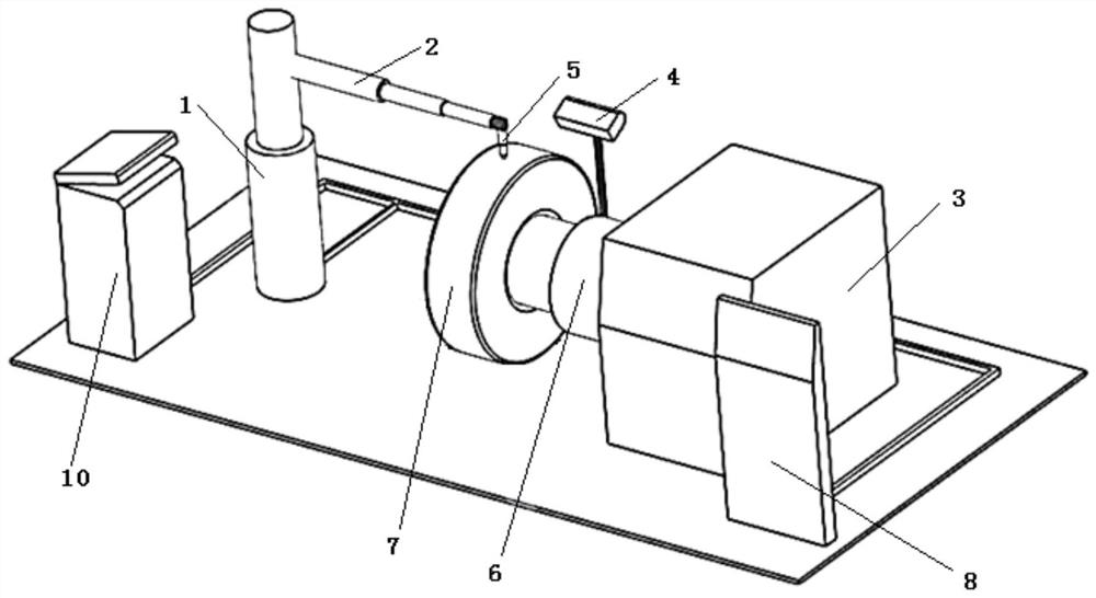
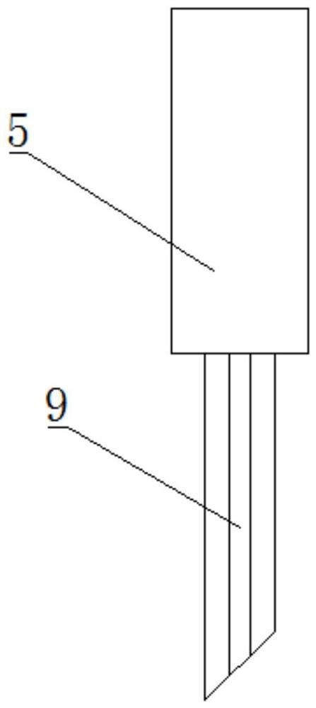
[0021] Such as figure 1 As shown, the present embodiment provides a tire engraving system, including a first electro-hydraulic push rod 1, a second electro-hydraulic push rod 2, a mount 3 and a scanner 4; the first electro-hydraulic push rod 1 is vertically The second electro-hydraulic push rod 2 is installed horizontally on the push rod of the first electro-hydraulic push rod 1, and the cutter head 5 is installed on the push rod of the second electro-hydraulic push rod 2; There is a rotating shaft 6, the rotating shaft 6 is driven by the drive motor through the bearing, the tire 7 is installed on the rim, and then installed on the rotating shaft 6 through the mounting hole bolts of the rim; For the camera, the first camera adopts a depth-of-field camera, and the first electro-hydraulic push rod 1, the second electro-hydraulic push rod 2, the drive motor and the depth-of-field camera are electrically connected to the controller 8 respectively.

[0022] working principle:

[...

Embodiment 2

[0026] On the basis of Embodiment 1, the scanner 4 also includes a second camera electrically connected to the controller 8, and the second camera monitors the pattern state of the surface of the tire 7 together with the depth of field camera, and feeds back to the controller 8, so that Play the role of calibrating the depth of field camera.

Embodiment 3

[0028] On the basis of Embodiment 2, the scanner 4 also includes a lamp electrically connected to the controller 8, the lamp is a commonly used marking lamp in the field, and the marking line drawn by the lamp is along the tire 7 axial direction. The direction is marked on the tire 7 surface, thereby the controller 8 can be quickly calibrated to the width of the tire 7.


PUM


Abstract

The invention discloses a tire engraving system, and belongs to the technical field of tires. According to the technical scheme, the system comprises a first electric hydraulic push rod, a second electric hydraulic push rod, a mounting base and a scanner. The first electric hydraulic push rod is vertically arranged, the second electric hydraulic push rod is horizontally installed on a push rod body of the first electric hydraulic push rod, and a tool bit is installed on a push rod body of the second electric hydraulic push rod. A rotating shaft is horizontally mounted on the mounting base andis driven by a driving motor, and a tire is mounted on the rotating shaft; and the scanner is located at one side of the tire, and the first electric hydraulic push rod, the second electric hydraulicpush rod, the driving motor and the scanner are electrically connected with a controller. The system is safe, efficient, high in precision and high in automation degree.

Description

technical field [0001] The invention relates to the technical field of tires, in particular to a tire engraving system. Background technique [0002] Finished new tires and old tires to be reproduced often face inappropriate patterns for different use environments and need to be adjusted or reproduced. Traditional finished tire rubber is difficult to cut and damage under manual operation, the tire is not easy to fix, and the engraving is difficult and the engraving accuracy is low. Contents of the invention [0003] The technical problem to be solved by the present invention is to overcome the deficiencies of the prior art and provide a tire engraving system which is safe, efficient, high in precision and high in automation. [0004] Technical scheme of the present invention is: [0005] The tire engraving system includes a first electro-hydraulic push rod, a second electro-hydraulic push rod, a mount and a scanner; the first electro-hydraulic push rod is installed verti...

Claims


Application Information

Patent Timeline
IPC IPC(8): B44B3/04B44B3/06B26D3/08B29D30/06
CPCB26D3/08B29D30/06B44B3/04B44B3/06B44B3/061
Inventor 李泉王洪磊
Owner 泰凯英(青岛)专用轮胎技术研究开发有限公司
Why Eureka
Try Eureka