Power rubber dinghy propeller structure

A technology for a propeller and a rubber boat is applied in the field of the propeller structure of a power rubber boat, which can solve the problems affecting the service life of the propeller, affecting the heat dissipation efficiency of the propeller, and adversely affecting the performance of the propeller, so as to improve the convenience and the heat dissipation effect. , the effect of improving performance

Inactive Publication Date: 2020-11-10
湖南洣水游艇制造有限公司
View PDF7 Cites 0 Cited by
  • Summary
  • Abstract
  • Description
  • Claims
  • Application Information

AI Technical Summary

Problems solved by technology

[0002] The propeller refers to the propulsion engine installed on the outside of the hull (ship side), which can be used for fishing leisure, water sports and other occasions. According to different energy sources, marine propellers are divided into two types: fuel propellers and electric propellers. The propellers usually use The engine is used as a power source. During the operation of the propeller, the power source or other components will generate heat. If the heat is not discharged in time, the temperature of the power source or other components will rise, affecting the performance of the propeller, and even causing damage to the propeller. , causing the propeller to be unusable. The current heat dissipation method of the propeller generally adopts the high-speed flow of air on the surface of the propeller to take away the heat for heat dissipation; The effect of achieving uniform heat dissipation greatly affects the heat dissipation efficiency of the propeller, which is not conducive to the better use of the propeller, affects the service life of the propeller, and is not conducive to the improvement of the performance of the propeller

Method used


Image

  • Power rubber dinghy propeller structure
  • Power rubber dinghy propeller structure
  • Power rubber dinghy propeller structure

Examples


Embodiment Construction

[0026] The technical solutions in the embodiments of the present invention will be clearly and completely described below in conjunction with the accompanying drawings in the embodiments of the present invention. Obviously, the described embodiments are only a part of the embodiments of the present invention, rather than all the embodiments. Based on the embodiments of the present invention, all other embodiments obtained by those of ordinary skill in the art without creative work shall fall within the protection scope of the present invention.

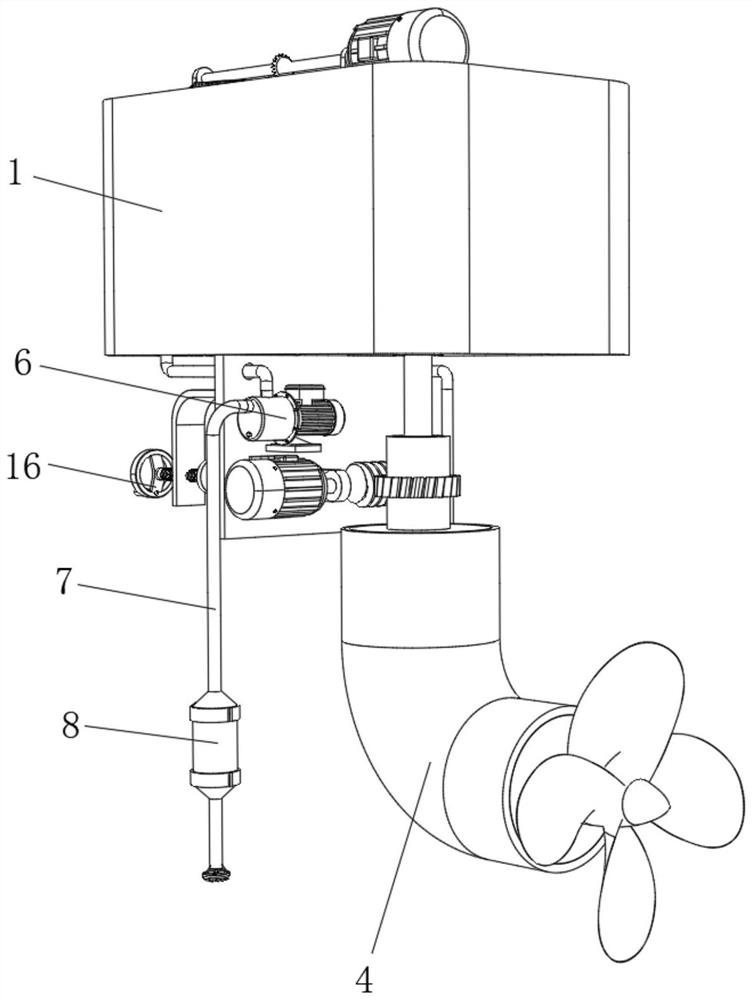
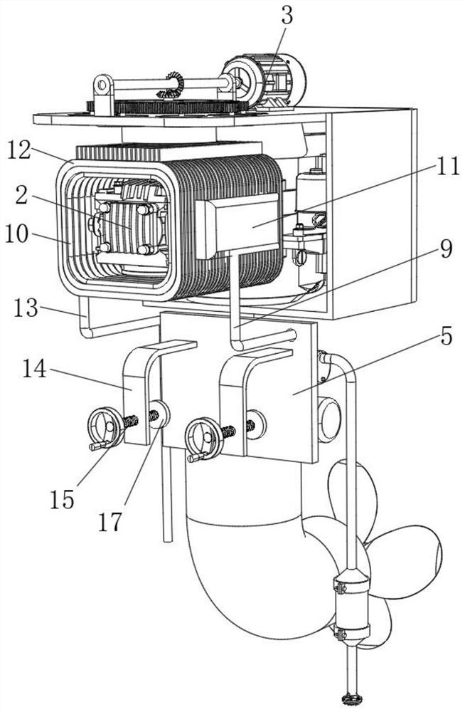
[0027] See Figure 1-5 , The present invention provides a technical solution: a power rubber boat propeller structure, including a propeller box 1, the propeller box 1 is provided with a propeller 2 inside, the specific model of the propeller 2 is 154F, and the propeller box 1 A ventilation and heat dissipation device 3 is provided on the upper surface of the propeller 2, a direction adjustment device 4 is provided at the output end of t...


PUM


Abstract

The invention relates to the technical field of thruster structures, and discloses a power rubber dinghy thruster structure which comprises a thruster box, a thruster is arranged in the thruster box,a ventilation and heat dissipation device is arranged on the upper surface of the thruster box, and a direction adjusting device is arranged at the output end of the thruster. A fixed vertical plate is fixedly connected to the lower surface of the propeller box, a water pump is fixedly connected to the back face of the fixed vertical plate, the input end of the water pump communicates with a waterinlet pipe, an impurity filtering device is arranged at the bottom of the water inlet pipe, and the output end of the water pump communicates with a water outlet pipe. According to the power rubber dinghy propeller structure, the star-shaped rotating fluted disc is driven by the driving motor to be matched with the rotating gear column, meanwhile, the suction fan and the auxiliary fan are drivento rotate to dissipate heat in the propeller box, the air flowing speed in the propeller box is effectively increased, the heat dissipation effect on the interior of the propeller box is improved, anduse convenience is improved.

Description

Technical field [0001] The invention relates to the technical field of propeller structures, in particular to a power rubber boat propeller structure. Background technique [0002] Propeller refers to the propulsion engine installed on the outside of the hull (ship's side), which can be used for fishing leisure, water sports and other occasions. According to different energy sources, marine propulsion is divided into two types: fuel propulsion and electric propulsion. Propellers are usually used The engine is used as the power source. During the operation of the propeller, the power source or other components will generate heat. If the heat is not discharged in time, the temperature of the power source or other components will rise, affecting the performance of the propeller, and even damage the propeller , Making the thruster unusable. The current heat dissipation method of the current thruster generally uses high-speed air flow on the surface of the thruster to take away heat f...

Claims


Application Information

Patent Timeline
Patent Type & Authority Applications(China)
IPC IPC(8): B63H21/38F01P1/00F01P5/04B63B34/20B01D29/03B01D29/56
CPCB01D29/03B01D29/56B63H21/383B63B34/20F01P1/00F01P5/04F01P2001/005
Inventor 卢芳旭颜周成阳怀英颜元武
Owner 湖南洣水游艇制造有限公司
Why Eureka
Try Eureka