
Computer cooling system

A heat dissipation system and computer technology, applied in the computer field, can solve the problems of computer hardware failure, low heat dissipation efficiency, poor heat dissipation effect, etc., and achieve the effects of speeding up air flow, convenient disassembly and installation, and protection from dust infestation.

Active Publication Date: 2019-01-15
广州大学华软软件学院
View PDF5 Cites 0 Cited by
  • Summary
  • Abstract
  • Description
  • Claims
  • Application Information

AI Technical Summary

Problems solved by technology

[0002] Computers are indispensable electronic products in our daily life and work. With the advancement of science and technology, the configuration of personal computers is getting higher and higher, which brings about the problem of hardware heat dissipation. If the heat dissipation effect of the computer case is poor, Not only will it speed up the aging of the internal lines of the chassis, but it will also cause the computer hardware to malfunction or even burn out in severe cases.
[0003] At present, cooling fans and heat sinks are used in most main computer cases to dissipate heat from the processor and graphics card on the main board. There are air holes for air flow on the main case, and the heat dissipation fan blows the heat on the heat sink into the main case. , and then one or two exhaust fans installed on the main chassis drive the air flow to discharge the hot air. The air circulation inside the main chassis of this cooling system is poor, and the external air passively enters the main chassis, resulting in low heat dissipation efficiency. , and during the heat dissipation process, the dust in the external air will also flow into the chassis. Under the action of static electricity, the dust will adhere to the motherboard and other components. After a long time, it will cause a short circuit on the motherboard or other components. loss to consumers

Method used


Image

  • Computer cooling system
  • Computer cooling system
  • Computer cooling system

Examples


Embodiment

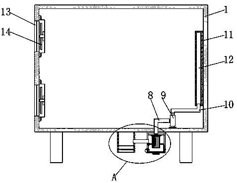
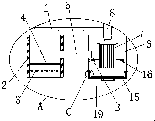
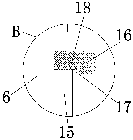
[0026] refer to Figure 1-Figure 6 As shown, a computer heat dissipation system is proposed in this embodiment, including a chassis 1, an air inlet tube 2 is fixedly installed at the bottom of the cabinet 1, and a coarse filter screen 3 and a first fine filter screen are fixedly installed on the inner wall of the air inlet tube 2 4. The first fine filter 4 is located above the coarse filter 3, and the bottom of the chassis 1 is located on one side of the air inlet tube 2. It is stipulated that a dust collection box 6 is installed, and the outer wall of one side of the air inlet tube 2 is fixed and connected. There is one end of the first air guide pipe 5, and the other end of the first air guide pipe 5 communicates with the dust collection box 6, the dust removal filter element 7 is fixedly installed in the dust collection box 6, and the negative pressure fan 9 is fixedly installed on the bottom inner wall of the chassis 1 The air inlet of the negative pressure fan 9 is fixedl...


PUM


Abstract

The invention belongs to the field of computer technology, in particular to a computer cooling system, including chassis, an air inlet cylinder is fixedly installed at the bottom of the chassis, a coarse filter screen and a first fine filter screen are fixedly installed on the inner wall of the air inlet cylinder, the first fine filter screen is located above the coarse filter screen, the bottom of the chassis is located at one side of the air inlet cylinder, and a dust collection box is arranged; one end of the first air duct is fixedly communicated with the outer wall of one side of the airinlet cylinder, and the other end of the first air duct is communicated with the dust collection box. The air supply mechanism with filtering function can actively convey loose and clean air into thechassis. In addition, the dust collecting groove on the dust collecting box arranged in the invention is convenient to disassemble and install, and is convenient to clean the dust regularly. The invention can accelerate the air flow speed in the chassis, not only has good heat dissipation effect, but also can effectively prevent the dust from pouring into the chassis, and protect the components inthe chassis from dust infection.

Description

technical field [0001] The invention relates to the technical field of computers, in particular to a computer cooling system. Background technique [0002] Computers are indispensable electronic products in our daily life and work. With the advancement of science and technology, the configuration of personal computers is getting higher and higher, which brings about the problem of hardware heat dissipation. If the heat dissipation effect of the computer case is poor, Not only will it accelerate the aging speed of the internal lines of the chassis, but in severe cases, it will also cause the computer hardware to malfunction or even burn out. [0003] At present, cooling fans and heat sinks are used in most main computer cases to dissipate heat from the processor and graphics card on the main board. There are air holes for air flow on the main case, and the heat dissipation fan blows the heat on the heat sink into the main case. , and then one or two exhaust fans installed on...

Claims


Application Information

Patent Timeline
IPC IPC(8): G06F1/18G06F1/20B01D46/00B01D46/12
CPCB01D46/0012B01D46/12G06F1/183G06F1/20B01D46/62
Inventor 周化
Owner 广州大学华软软件学院
Learn More